4
Operating instructions
Safety-monitoring module
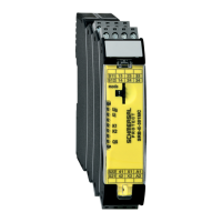
SRB-E-301MC
EN
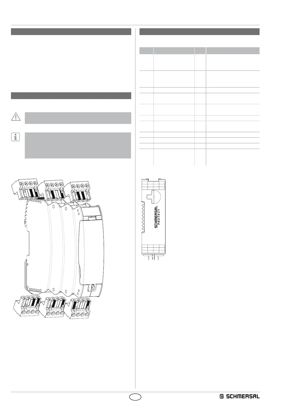
3. Mounting
3.1 General mounting instructions
Mounting: snaps onto standard DIN rails to IEC 60715.
Hook bottom of enclosure in DIN rail and push down until it engages in
position.
3.2 Dimensions
All measurements in mm.
Device dimensions (H/W/D): 98 x 22.5 x 115 mm
4. Electrical connection
4.1 General information for electrical connection
The electrical connection may only be carried out by
authorised personnel in a de-energised condition.
To avoid EMC disturbances, the physical ambient and
operational conditions at the place where the product is
installed, must meet the provisions laid down in the
paragraph "Electromagnetic Compatibility (EMC)" of
DIN EN 60204-1.
4.2 Coding of connecting terminals
5. Operating principle and settings
5.1 Description of the terminals and LED indications
Pin Function LED Function
A1 Operating voltage
+ 24 VDC
24 VAC
U
B
U
i
Operating voltage OK
Internal fuse OK
A2 Operating voltage
0 V
24 VAC
QS Cross-wire monitoring active
X1 Output start circuit /
feedback circuit
X2 Input start circuit /
feedback circuit
S11 Output channel 1 +24 VDC
S21 Output channel 2 +24 VDC without QS
0 V with QS
S12 Input channel 1 K1 Status K1
S22 Input channel 2 K2 Status K2
41/42 Signalling contact (NC)
13/14,
23/24,
33/34
Safety outputs
1
S11 13 23 33
342414S12
A1X141S22
SRB-E-301MC
A2X242S21
U
i
K1
K2
QS
mode
U
B