6
Operating instructions
Safety-monitoring module
SRB-E-301MC
EN
6. Diagnostic
6.1 LED indicators / malfunctions
LED Function Display type
U
B
Ready for operation Continuously lit
No operating voltage at A1 and A2 Not lit
U
i
Operationally ready and internal fuse OK Continuously lit
No operating voltage at A1 and A2
Not lit
Internal fuse triggered
K1
Relay channel 1 active Continuously lit
Input S12 open, relay K1 deactivated
Not litManual start signal, feedback circuit missing
Invalid rotary switch setting
K2
Relay channel 2 active Continuously lit
Input S22 open, relay K2 deactivated
Not litManual start signal, feedback circuit missing
Invalid rotary switch setting
7. Wiring examples
7.1 Possible applications
All applications for 1 or 2-channel safe evaluation for protective
equipment as follows:
• Safety door monitoring to ISO 14119
• Position switches with positive break to IEC 60947-5-1
• Safety sensors to EN 60947-5-3
• Emergency stop command devices to ISO 13850 and IEC 60947-5-5
• Magnetic safety sensors to EN 60947-5-3
• Safety light curtain and photoelectric barriers according to IEC 61496
The connection of magnetic safety switches to the SRB-E-...
safety-monitoring module is only admitted when the
requirements of the standard IEC 60947-5-3 are observed.
As the technical data are regarded, the following minimum
requirements must be met:
•
Switching capacity: min. 240 mW
•
Switching voltage: min. 24 VDC
•
switching current: min. 10 mA
For example, the following safety sensors meet the
requirements:
•
BNS 36-02Z(G), BNS 36-02/01Z(G)
•
BNS 260-02Z(G), BNS 260-02/01Z(G)
When sensors with LED are wired in the control circuit
(protective circuit), the following
rated operating voltage must be observed and respected:
• 24 VDC with a max. tolerance of –5%/+20%
Otherwise availability problems could occur, especially in
series-wired sensors, where a voltage drop in the control
circuit is triggered by LED's for instance.
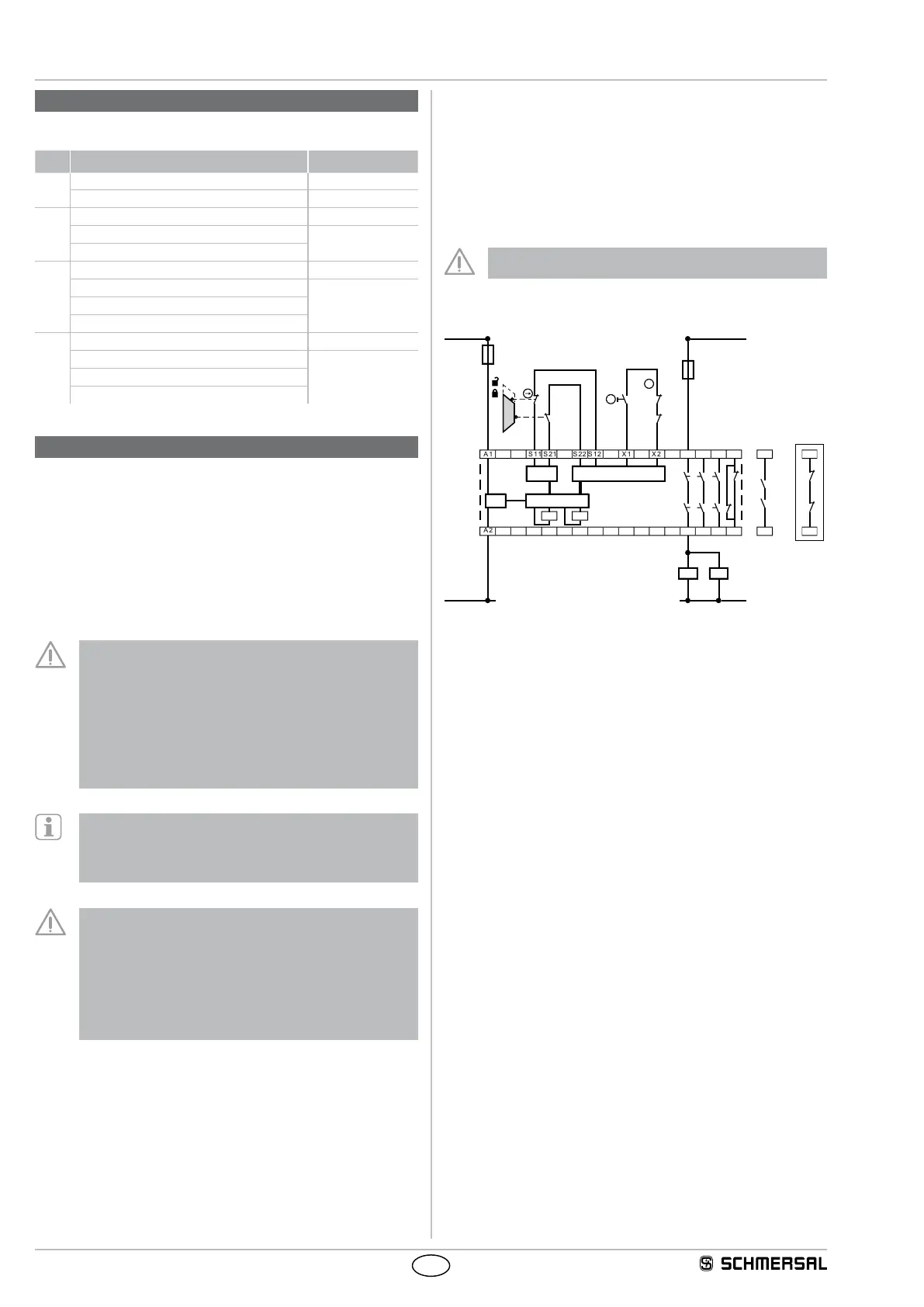
7.2 Application example
Dual-channel control, shown for a guard door monitor with
two position switches where one has a positive break contact;
with external reset button
J
• Relay outputs: Suitable for 2-channel control, for increase in capacity
or number of contacts by means of contactors or relays with positive-
guided contacts
• H2 = Feedback circuit
Signalling outputs must not be used in safety circuits.
Wiring example
X2A1 S22S11
A2
S21X1S12
K
A
0V / GND
K
B
K
A
K
B
K
A
K
B
F1
K1 K2
K2
K1
2313 33 41
2414 34 42
N
R
H2
41
42
Option 20
a)d)
e)f)
Key
a) Safety inputs
d) Outputs
e) Processing
f) Power