7
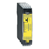
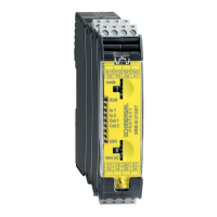
SRB-E-301MC
Operating instructions
Safety-monitoring module
EN
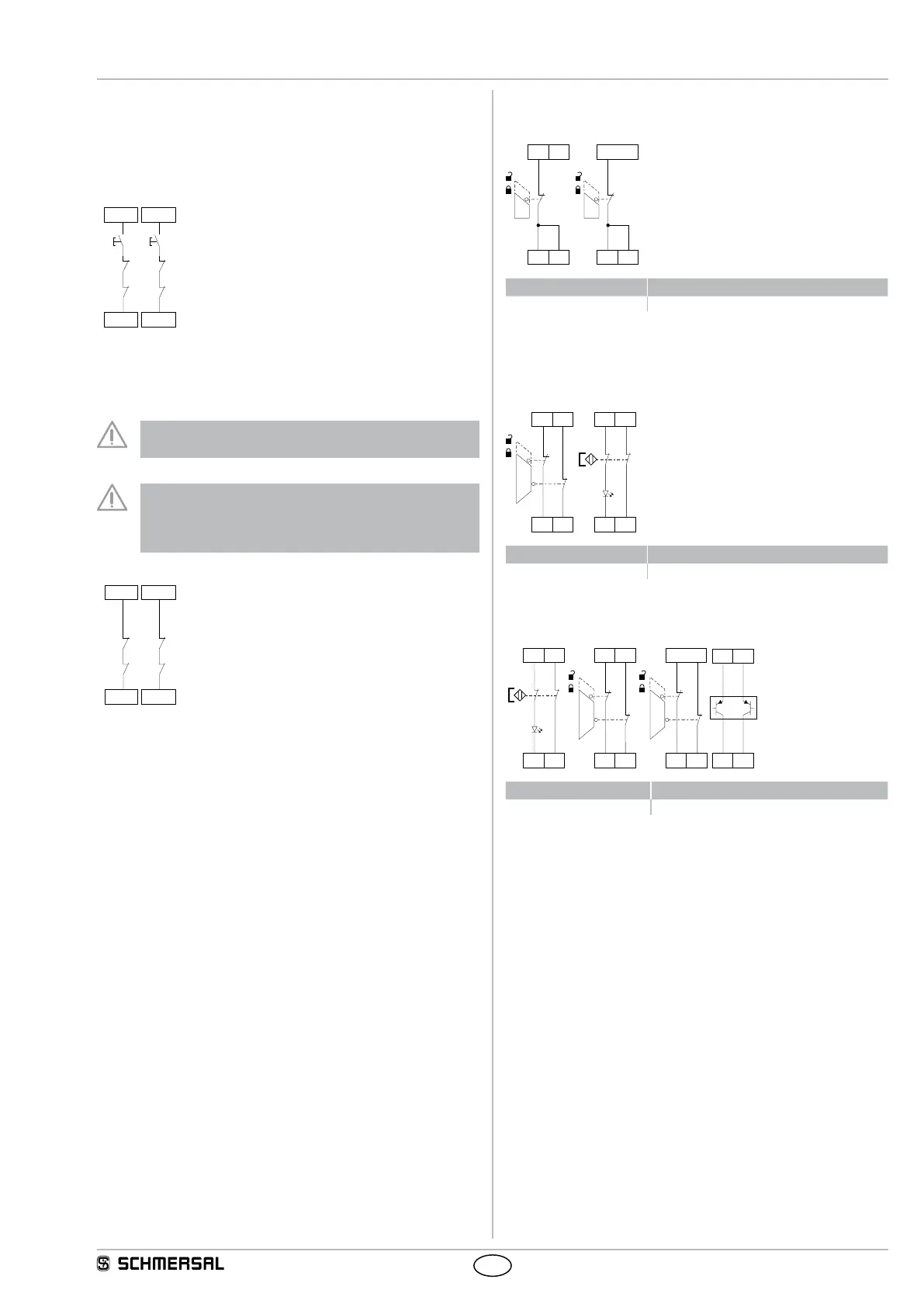
7.3 Start configuration
7.3.1 External reset button
•
The external reset button is integrated in the feedback circuit in series.
• The manual start or the activation of the module occurs when the
button is pressed (not when it is released!).
X2
J
X1
X2
+24 VDC
K
B
K
A
J
K
B
K
A
7.3.2 Feedback circuit / Automatic start
• The automatic start is programmed by connecting the feedback circuit
to the terminals X1-X2. If the feedback circuit is not required, establish
a bridge.
Not admitted without additional measure due to the risk of
gaining access by stepping behind!
Within the meaning of IEC/EN 60204-1 paragraph 9.2.5.4.2
the operating mode "automatic start" is only restrictedly ad-
missible. In particular, any inadvertent restart of the machine
must be prevented by other suitable measures.
X2
X1
X2
+24 VDC
K
B
K
A
K
B
K
A
7.4 Sensor configuration
Single channel signal processing
+24 VDC
S12 S22 S12 S22
S11 S21
Rotary knob position Function
2, 6, 10, 14 without cross-wire monitoring
Dual channel signal processing NC / NC
With cross-wire monitoring
(Category 4 – PL e to ISO 13849-1 possible)
S12 S22
S11 S21
S12 S22
S11 S21
Rotary knob position Function
1, 5, 9, 13 with cross-wire monitoring
Without cross-wire monitoring
(Cat. 4 - PL e to ISO 13849-1 only possible with protective wiring)
S12 S22
S11 S21
S12 S22
S11 S21
+24 VDC
S12 S22
S12
+24V
S22
+24V
Rotary knob position Function
2, 6, 10, 14 without cross-wire monitoring