32
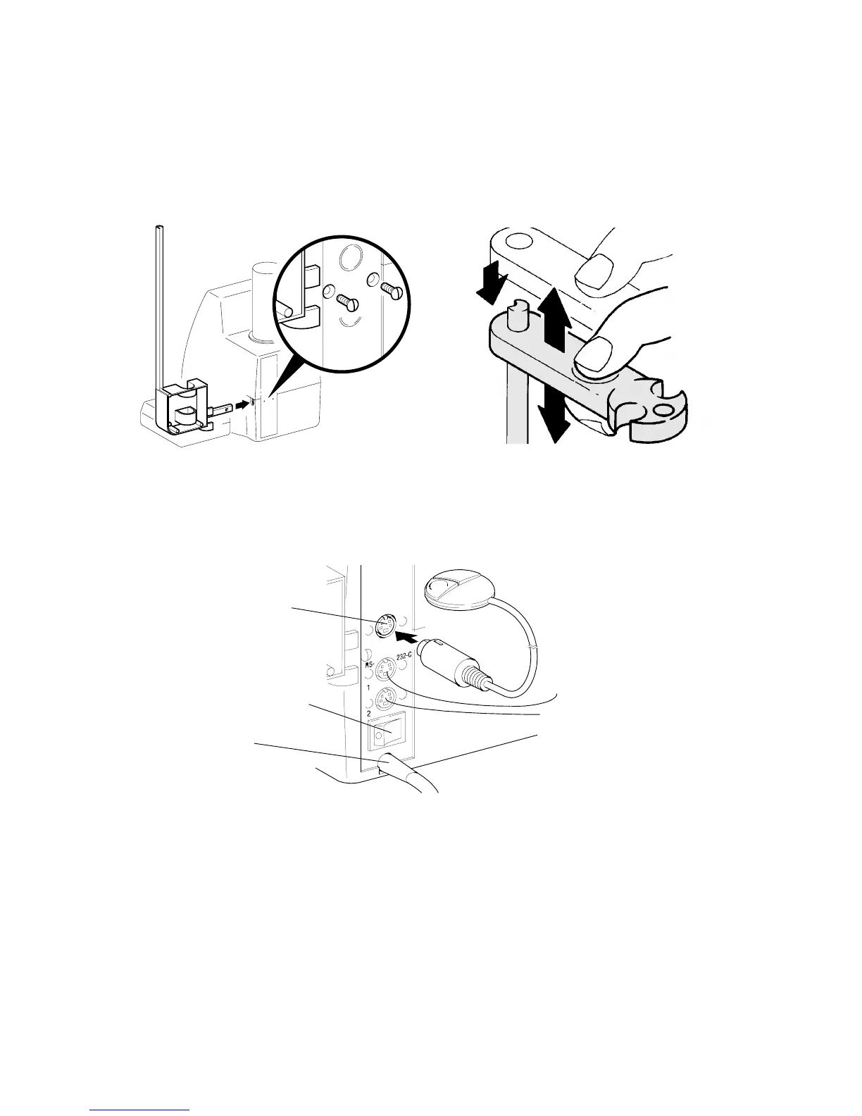
3.3 Installation of the stand
Insert the TZ 3665 Stand Rod at the right side (& Fig. 5) and fasten it on the back panel of the
TITRONIC
â
ââ
â
universal Piston Burette using the two included M3 x 10 mm screws (slot-screw driver). Install
the electrode / titration-tip holder as is shown in Fig. 6.
Fig. 5 Installation of the stand
Fig. 6 Installation, lifting and lowering the
electrode / titration-tip holder
3.4 Connecting the manual key button and a printer / computer (PC);
switching on and off
Fig. 7
Mains switch (on / off)
Mains cable
Interface 2: RS-232-C
Connector for
manual key button
Interface 1: RS-232-C
The transfer parameters for the RS-232-C interface can be selected according to & “RS-232-C interface”
chapter.
Attention: The design of the three 4-channel sockets is identical. If the plugs are interchanged,
the electronics of the TITRONIC
â
ââ
â
universal Piston Burette may be damaged.
Upper socket: manual key button;
Middle socket: printer / computer (PC); –interface 1–
Lower socket: Daisy chaining of several TITRONIC
â
ââ
â
universal Piston Burettes,
please refer to & Daisy-changing of devices’, chapter, –interface 2–
Ü Connect the mains plug to mains.
Ü The main switch is located on the back panel of the TITRONIC
â
ââ
â
universal Piston Burette.