Technical data
24 03.00 | FT | Assembly and Operating Manual | en | 389582
3.4 Maximum permissible load
The following diagrams show the maximum permissible load in
which the force-torque-sensor may be used and when it can lead
to damage. Each page covers one size. The upper diagram shows
the interplay of forces in the X or Y direction in combination with
torques in the Z direction. The lower diagram shows the interplay
of forces in the Z direction in combination with torques in the X or
Y direction. Each diagram includes several SI calibrations.
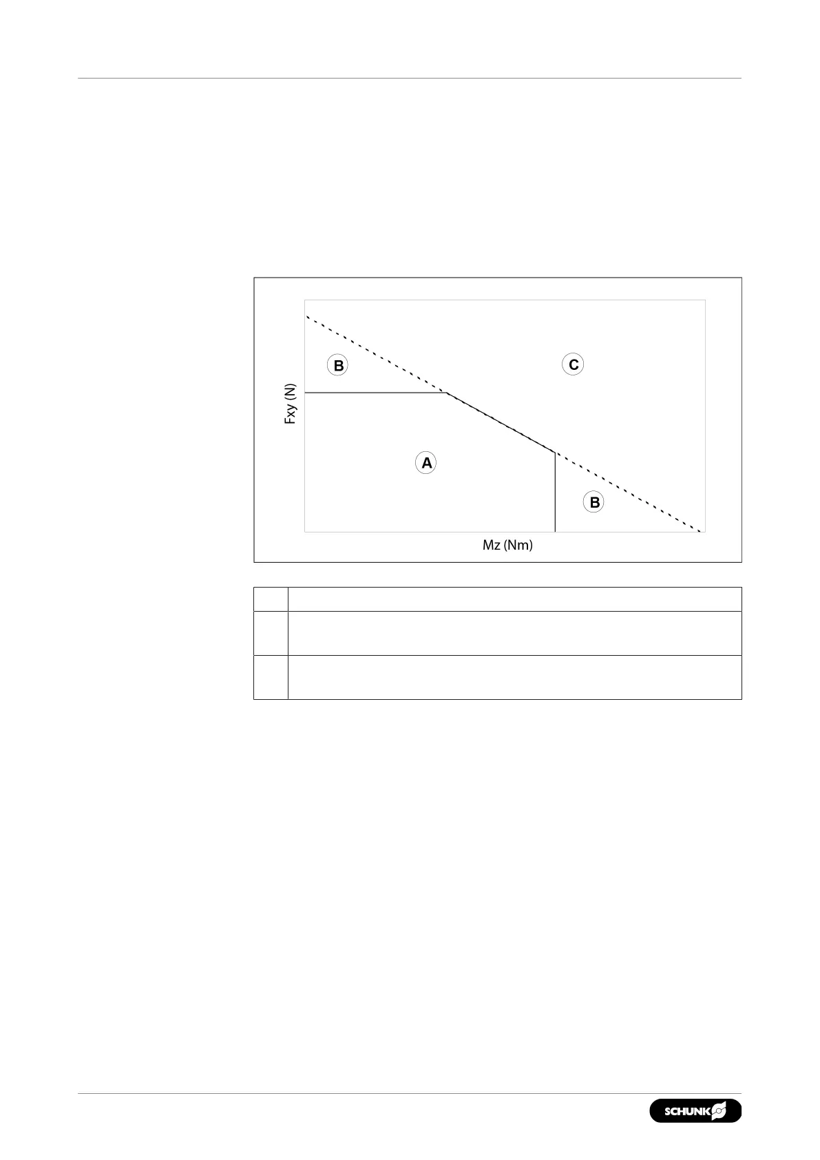
Example diagram with maximum permissible load of a force-torque-sensor
A In this range, the force-torque-sensor functions perfectly.
B In this range, the force-torque-sensor still functions perfectly,
but the measured values may deviate.
C In this range, the strain gages are in saturation, and the
force-torque-sensor may get damaged.