Assembly
14
03.00 | PWG-S | Assembly and operating manual | en | 389361
4 Assembly
4.1 Connections
4.1.1 Mechanical connection
WARNING
Risk of injury due to unexpected movements!
If the power supply is switched on or residual energy remains in
the system, components can move unexpectedly and cause
serious injuries.
• Before starting any work on the product: Switch off the power
supply and secure against restarting.
• Make sure, that no residual energy remains in the system.
Evenness of the
mounting surface
The values apply to the whole mounting surface to which the
product is mounted.
Requirements for evenness of the mounting surface (Dimensions in mm)
Edge length Permissible unevenness
< 100 < 0.02
> 100 < 0.05
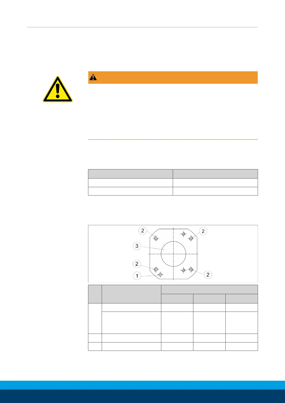
Mounting
Fasten the gripper to the base surface using four threaded holes.
A centering bore and fixing bore are in the base surface in order to
position the gripper.
Item Designation PWG-S
40 60 80
1 Mounting thread M4 M5 M6
Max. depth of
engagement from
locating surface [mm]
10 14 16
2 Centering bore [H7] Ø20H7 Ø25H7 Ø40H7
3 Fixing bore [H7] Ø4H7 Ø4H7 Ø5H7

 Loading...