Steps 1 & 2
Step 3
Step 4
Step 1
Inspect the cable connection at the left upper handlebar
Tools Required: Estimated Time to Complete: Service Manual Procedure:
Phillips head screwdriver
6mm hex key/Allen wrench
5 minutes Replace the Cables (Section 3)
Access the connection
Important: Unplug the power cord from both the front of your machine and the electrical
outlet before continuing
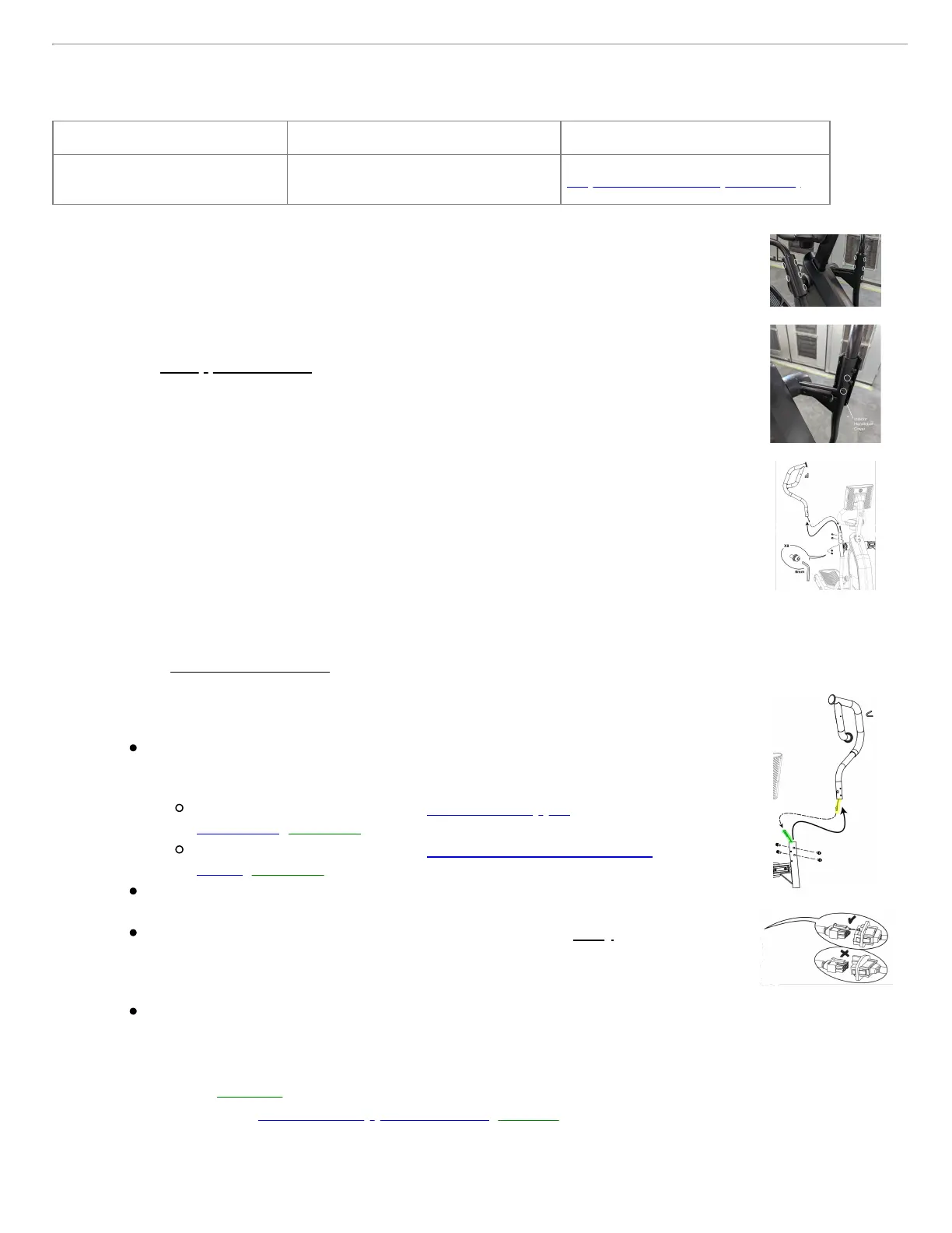
1. The upper and lower handlebar connection is protected by a handlebar cover. Five
tabs on the external cover snap into place on the interior cover to secure it in place.
2. On the left upper handlebar, gently compress the outside of the exterior cover to
release the tabs. Remove the exterior cover and set it to the side.
3. Next, locate the two screws facing the main body of the machine - these are used to
attach the interior cover. Use a Phillips head screwdriver to loosen and remove the
screws, then set the interior cover aside.
4. Once the handlebar cover is removed, we can use a 6mm Allen wrench to loosen
and remove the four screws connecting the upper and lower handlebar.
5. Slightly pull up on the upper handlebar to expose the cable connection for incline
controls.
Check the handlebar cable
1. There is one cable connection between the Base Hub (circuit board controlling
resistance, speed, and incline) and the upper handlebars.
2. Let's unplug the cable so we can check the following items:
Damage - Check for cut, crimped, or frayed wires, loose connectors, and
missing/bent pins within the connectors. If a cable or connector is
damaged, the replacement item depends on which cable is affected:
Cable from Upper Handlebar: order a Left Upper
Handlebar [15333.F1].
Cable from Lower Handlebar: order a Base Hub to Buttons
Cable [15333.F2].
Connector Orientation - the color of the wires should match on both sides of
the connection (e.g., red wire matches red wire).
Connection Tightness - the cable connectors must be firmly pressed
together to properly secure the connection. The connectors have a latching
mechanism where a plastic tab on the male connector slides over a small
ridge on the female connector.
These latch components can also be used to confirm the connectors are
secured in the correct orientation.
2. Once the cable is reconnected, test if the issue persists. Be careful not to pinch the wire when reinstalling
the handlebar [15333.G].
3. If the issue persists, order a Left Upper Handlebar [15333.J].
 Loading...