58
SCION xA (EM00D0U)
Engine Control
2. Control System
∗ SFI system
The SFI system monitors the engine condition through the signals, which are input from each sensor to the engine
control module. The best fuel injection volume is decided based on this data and the program memorized by the engine
control module, and the control signal is output to TERMINALS #10, #20, #30 and #40 of the engine control module to
operate the injector. (Inject the fuel). The SFI system produces control of fuel injection operation by the engine control
module in response to the driving conditions.
∗ ESA system
The ESA system monitors the engine condition through the signals, which are input to the engine control module from
each sensor. The best ignition timing is detected according to this data and the memorized data in the engine control
module, and the control signal is output to TERMINALS IGT1, IGT2, IGT3 and IGT4. This signal controls the ignition coil
and igniter to provide the best ignition timing for the driving conditions.
∗ IAC system
The IAC system increases the RPM and provides idling stability for fast idle–up when the engine is cold and when the
idle speed has dropped due to electrical load, etc. The engine control module evaluates the signals from each sensor,
outputs current to TERMINAL RSD, and controls the idle air control valve.
∗ Fuel pump control system
The engine control module operation outputs to TERMINAL FC and controls the C/OPN relay. Thus controls the fuel
pump drive speed in response to conditions.
3. Diagnosis System
With the diagnosis system, when there is a malfunctioning in the engine control module signal system, the malfunction
system is recorded in the memory. The malfunctioning system can then be found by reading the display (Code) of the
malfunction indicator lamp.
4. Fail–Safe System
When a malfunction occurs in any system, if there is a possibility of engine trouble being caused by continued control based
on the signals from that system, the fail–safe system either controls the system by using data (Standard values) recorded in
the engine control module memory or else stops the engine.
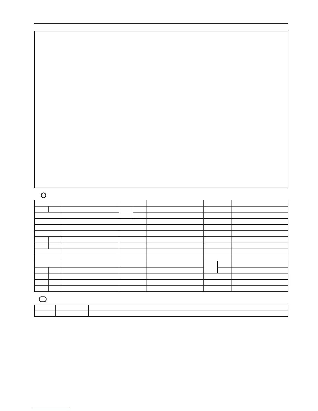
: Parts Location
Code See Page Code See Page Code See Page
A10 C 30

 Loading...