34 EN
H
Photocells 1
function
H-0 Stand-by
The factory setting is « H-0 »
H-1 Ready
L Stop command
L-0
Close
The factory setting is « L-0 »
Exit 11 and 12
L-1
Open
P
Remote control
function
P-1
Close
The factory setting is « P-1 »
P-2
Open
D4- Testing and checking
Make sure the general safety precaution «WARNING» has been carefully observed :
• Release the gearmotor with the proper release key.
• Make sure the gate can be moved manually during opening and closing phases with a force of max
390N (40 kg approx).
• Lock the gearmotor.
• Using the key selector switch, push button device or the radio transmitter, test the opening, closing and stopping
of the gate and make sure the gate is in the intended direction.
• Check the devices one by one (photocells, blinker, key selector, etc.) and confirm the control unit recognizes
each device.
D5- Recognition of LED
LED indications Descriptions
LED 1 Photocells
The LED1 turns on, when there is an obstacle between the photocells or an aligning
defect or a connection defect (Be carefull, function H must be activated with a connected
photocell on PH1).
LED 2 Photocells
The LED2 turns on, when there is an obstacle between the photocells or an aligning
defect or a connection defect (Be carefull, function J must be activated with a connected
photocell on PH2).
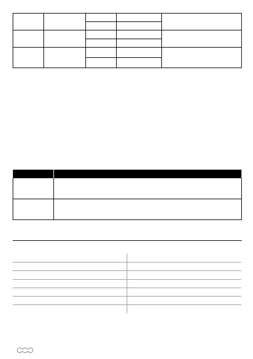
Motor motor 12V DC
Gear Type sliding
Motor Speed 2600 rpm/min
Maximum gate weight/ Maximum gate length 400 kg / 4 m
Operating temperature -20°C~+50°C
Speed 23.10 cm/s
Dimensions 309 mm x 157 mm x 308 mm
Motor
E- TECHNICAL FEATURESE- TECHNICAL FEATURES