Do you have a question about the Scytek electronic A4.2W SERIES and is the answer not in the manual?
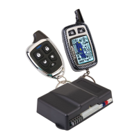
Lists system components and optional features for system personalization.
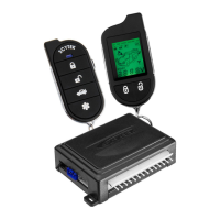
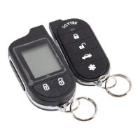
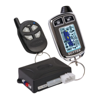
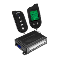
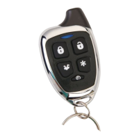
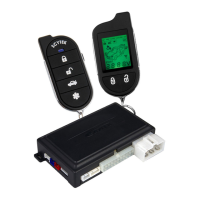
Explains the functions of each button on the G Series and A Series remote transmitters.
Describes transmitter functions and how to perform system programming.
Explains two-car operation and how to replace transmitter batteries.
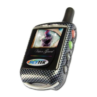
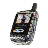
Explains LCD transmitter pages, icons, and battery replacement.
Details on setting auto daily start times for the control unit and pager.
Explains Power Save mode and how to activate the LCD backlight.
How to check system status and overview of programmable functions.
Instructions on how to arm, lock, disarm, and unlock the system using the remote.
Explains the process of automatic arming when the ignition is off and doors are closed.
How to activate panic mode and perform emergency system disarming.
Steps to activate Valet Mode and use the Driver Calling/Page feature.
Step-by-step instructions for remote starting and shutting down the vehicle engine.
Explains the Quick Stop feature to leave the engine running when exiting the vehicle.
Explains the optional Turbo Timer feature for turbocharged engines.
Steps for preparing, starting, and shutting down manual transmission vehicles remotely.
Explains ignition locking/unlocking, dome light, auxiliary outputs, and sensor disabling.
Covers pre-installation checks, hood pin mounting, and component placement.
Guidance on selecting suitable interior mounting locations for key system components.
Details wiring for starter harness, main harness, door locks, and shock sensor.
Details connectors for sensors, valet switch, LED, and door locks.
Selects the polarity (+/-) for the on-board Parking Light relay output.
How to enter programming mode and reset system parameters using different remotes.
A table detailing programmable features and how to access their descriptions.
Describes antenna components and explains starter diagnostic flash codes.
Details wiring for starter harness, main harness, door locks, and shock sensor.
Diagrams for dome light activation, horn honk, and clutch switch relay circuits.
Relay diagrams for starter defeat/anti-grind and negative glow plug inputs.
Diagrams for negative trigger, positive trigger, reverse polarity, and vacuum door locks.
Diagram for adding aftermarket actuators to door lock systems.
Diagrams for two-stage negative and positive trigger door lock connections.
Diagrams for two-stage reverse polarity and adding actuators.
| System Type | Car Alarm |
|---|---|
| Remote Start | Yes |
| Keyless Entry | Yes |
| Number of Remotes | 2 |
| Sensor Type | Dual Zone Shock Sensor |
| Siren Output | 120dB |
| Voltage Range | 12V DC |
| Operating Frequency | 433.92 MHz |
| Anti-Theft Protection | Yes |
| Valet Mode | Yes |
| Shock Sensor | Dual Zone |
| Immobilizer | Yes |