5/22 Ref. GPAO : 33502017201_1_1
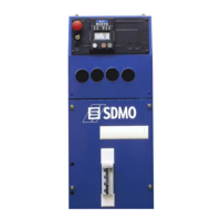
Fig. 2.2 – Description of the LEDs
A lit LED indicates:
c Module being supplied (green, lights up and remains lit)
d Emergency stop activated (control panel or external emergency stop) (red, lights up and remains lit)
e Visualisation of starting phase and speed/voltage stabilisation (flashing) and generating set operating OK or set ready to
generate (green, lights up and remains lit)
f General alarm (orange, flashing)
g General fault (red, flashing).
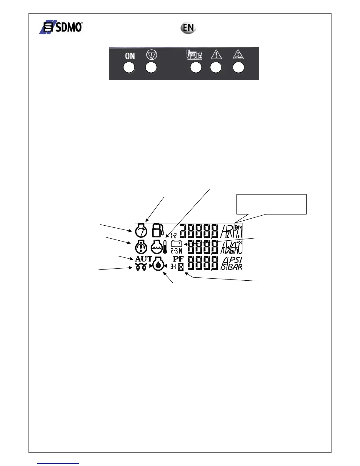
2.1.2 Introduction to pictograms
The pictograms are as follows:
Operating temperature
Fuel
Overspeed
Non-starting fault
Starting on external command
Preheating
Air intake
Oil pressure
Battery
Delay
Fig. 2.3 – View of pictograms
¾ The "fuel level" pictogram is used to display the fault, the alarm and the fuel level.
¾ The "operating temperature" and "oil pressure" pictograms are used to display the fault and analog value
¾ The "overspeed" and "non-starting fault" pictograms are used to display the fault.
¾ The "battery" pictogram is used to display the "alternator charge" fault and to indicate the battery voltage.
1 2 3 4 5
Symbols for electric and
mechanical sizes