6/22 Ref. GPAO : 33502017201_1_1
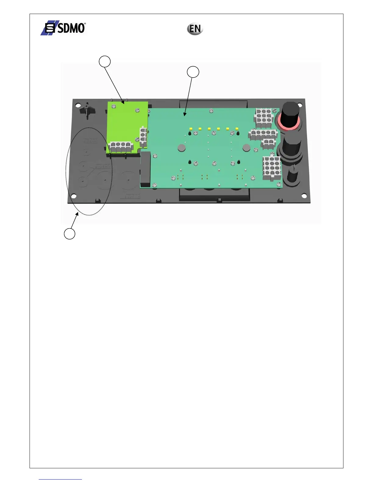
2.1.3 Introduction to the rear panel
Fig. 2.4 – View of the front side
c "Base" electronic card
d "Measurements" electronic card (optional if the power rating of the generating set is less than 30 kVA)
e Slot for options.
2.2. Safeguards
The following options may be added to the standard configuration:
o Measurements card (if the power rating of the generating set is less than 30 kVA)
o Connected directly to the base card, used for measuring and displaying:
- Electrical quantities (phase-to-neutral voltages "V" and phase-to-phase voltages "U", phase currents
"I")
- Analogue motor quantities (oil pressure, temperature of coolant and level of fuel in daily service tank)
o Auto. pack
9 Comprising a preheating switch for the motor cooling circuit, a 12 V – 2.5 A charger connected to the Nexys
module via a wiring harness, a terminal block (2 terminals) and a wiring harness for connecting the external
starting command
o External starting command
9 2-strand wiring harness with customer connection to 2 terminals on the control console
o Report pack (remote information report)
9 Provides the following information, on voltage-free switch:
Generating set ready to generate
General fault
Low fuel level fault or alarm (depending on configuration)
o Speed potentiometer
9 Used for adjusting the motor speed by means of a potentiometer located in the panel fascia (this adjustment is
only possible for motors equipped with an electronic regulation system)
o Voltage potentiometer
9 Used for adjusting the alternating voltage supplied by the alternator by means of a potentiometer located in the
panel fascia (the potentiometer must be connected to a regulator enabling external adjustment)
3
2
1