Product Manual - Hawk 1 Family SCSI-2 (Volume 1), Rev. D
_____________________________________________________________________________________
11.6.4 Electrical description
Model ST11200N/NC uses single ended interface signals. These signals must be terminated with 110 ohm
active termination circuits at each end of the total cable. Single Ended circuits use open collector or three
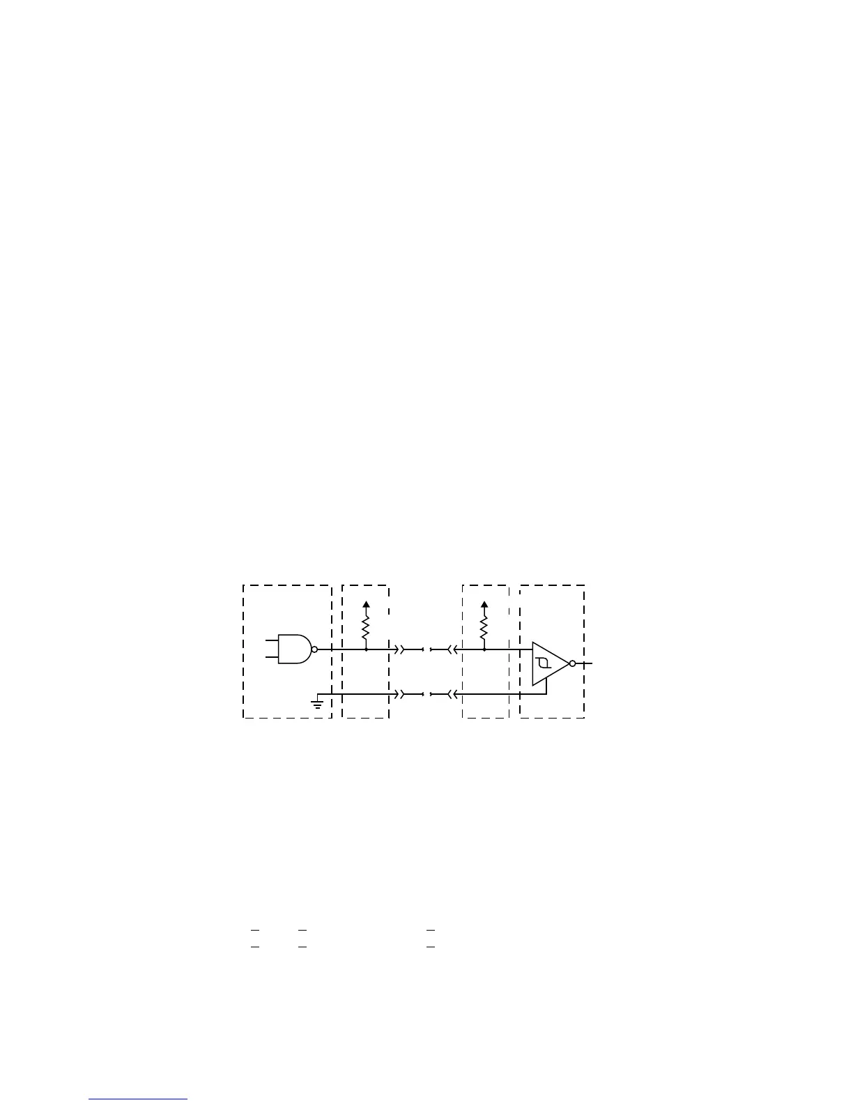
state drivers. See Figure 11.6.4-1 and 11.6-1.
The model ST11200ND uses differential interface signals and each of these must be terminated at each end
of the total cable with 330 ohms to +5 V and 330 ohms to ground with 150 ohms between each differential
pair. All I/O circuits are open collector, three state drivers. See Figure 11.6.4-2 for circuit drawing. Differential
I/O drives are shipped without terminators. These drives have no provisions for adding terminator sockets
on the PCB. On these drives some method of external termination must be provided by the user.
11.6.4.1 Single ended drivers/receivers
Typical single ended driver and receiver circuits for the ST11200N/NC is shown in Figure 11.6.4-1. Termina-
tor circuits shown (Note [1]) are needed only when the disc drive is first or last in the daisychain.
Note. ALL TERMINATORS MUST BE ANSI SCSI-2 ALTERNATIVE 2 ACTIVE TERMINATORS.
Transmitter characteristics
Single ended drives use an ANSI SCSI compatible open collector single ended driver. This driver is capable
of sinking a current of 48 mA with a low level output voltage of 0.4 volt.
Receiver characteristics
Single ended drives use an ANSI SCSI single ended receiver with hysteresis gate or equivalent as a line
receiver.
[1] Part of active terminator circuits. Removable terminator resistor packs, used in the drive when it is first
or last in the daisychain.
The difference in the voltages between input and outgput signals is due to the losses in the cable.
[2] ANSI SCSI compatible circuits
[3] Total interface cable length should not exceed that specified in paragraph 11.6.2.2.1.
[4] Source of drive terminator power is a semiconductor voltage regulating device which has an input
source voltage selected by jumper plug.
[5] Interface signals levels and logical sense at the drive I/O connector are defined as follows:
Logic Level Driver Output Receiver Input
Negated (0) >2.5 V: <5.25 V >2.0 V: <5.25 V
Asserted (1) <0.4 V: >0.0V <0.8 V: >0.0 V
The difference in the voltages between input and output signals is due to the losses in the cable.
Figure 11.6.4-1. Single ended transmitters and receivers
Transmitter
(or transceiver)
Line Driver
Flat
Cable
Pair
[3]
[2]
[4]
[1]
+2.85V
110
Ohm
[4]
[1]
+2.85V
110
Ohm
Receiver
Line Receiver
[2]
[5]
63