Product Manual - Hawk 1 Family SCSI-2 (Volume 1), Rev. D
_____________________________________________________________________________________
Notes.
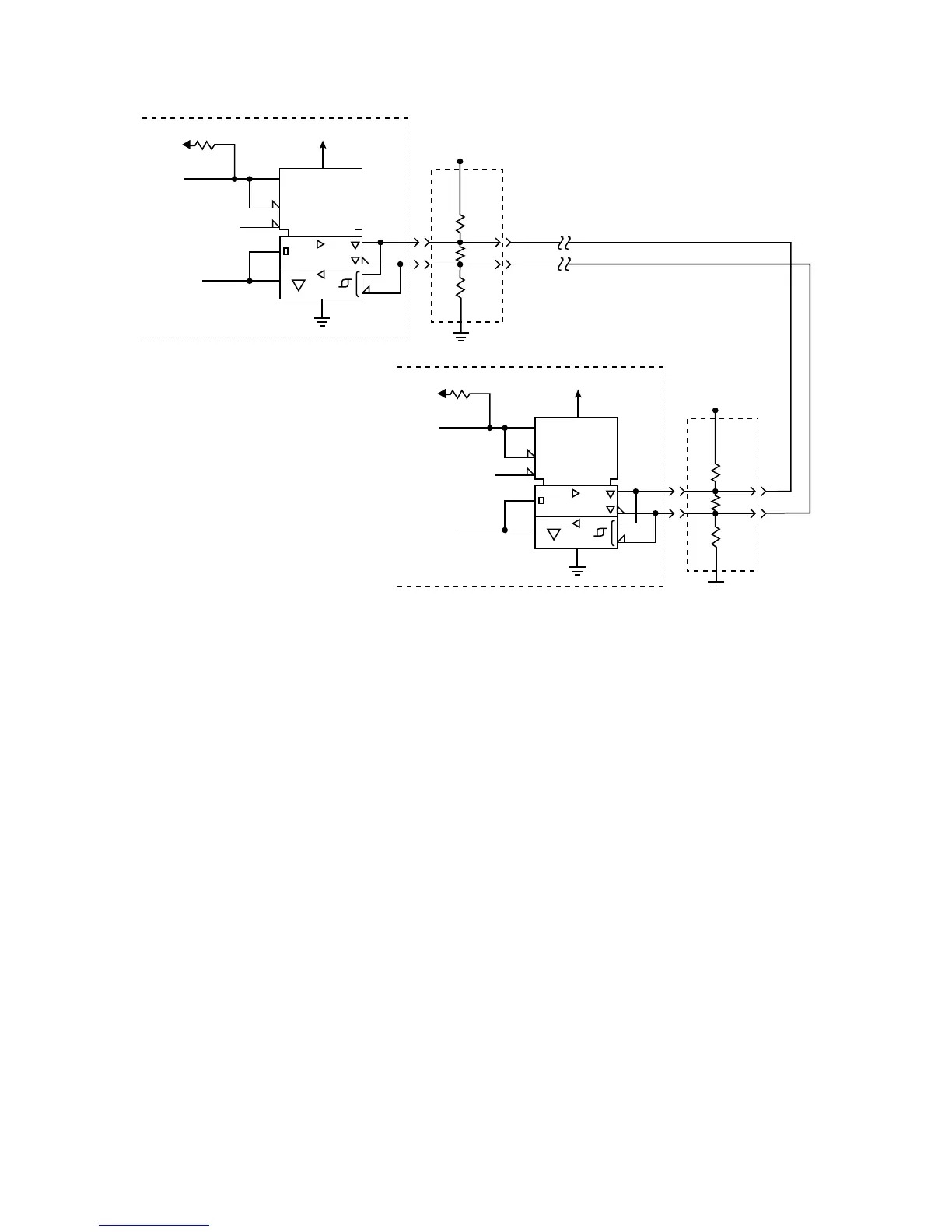
[1] Positive Logic Enables Transmitter (+5 V = Asserted)
Negative Logic Enables Receivers (0 V = Asserted)
[2] Negative Logic Signal (0 V = Asserted)
[3] Total interface cable length should not exceed value given in paragraph 11.6.2.2 from first SCSI device
at beginning to end of daisychain. See section 11.6.4.2 for signal characteristics.
[4] I/O Line terminators. If SCSI device is a Seagate disc drive, terminators and a place to plug them in
must be provided external to the drive by user or systems integrator where needed. The drive has no
terminators and there are no provisions on the drive for terminator installation.
[5] Arrangements for connecting terminator power to the terminators must be made by the systems de-
signer. As a help, drive +5 V power is made available on SCSI bus pin 26 for powering external termina-
tors if the drive option select header jumper (Figure 10.1-1a) is installed in position 8.
[6] SCSI I/O line (pin 21) disables I/O circuits if single-ended cable plugged in or cable plugged in upside
down.
[7] SCSI I/O cable ground. See Table 11.6.3-1b.
Figure 11.6.4-2. Typical differential I/O line transmitter/receiver and terminators
TE
RE
LSI
XCVR
1
1
R2
+5V
+5V
5.6K
Transmit/Receive
Enable (1)
Transmit or
Receive
Signal (2)
(3)
Term
Power
(5)
330
Ohm
150
Ohm
330
Ohm
SCSI Device at Beginning of I/O Cable
(usually Host Adaptor/Initiator)
TE
RE
LSI
XCVR
1
1
R2
+5V
+5V
5.6K
Transmit/Receive
Enable (1)
Transmit or
Receive
Signal (2)
Term
Power
(5)
330
Ohm
150
Ohm
330
Ohm
SCSI Device at End of I/O Cable
(Drive/Target)
(4)
Twisted or Flat
Cable Pair
(4)
DIFFSENS (6) Disable
DIFFSENS (6)
Disable
(7)
(7)
65