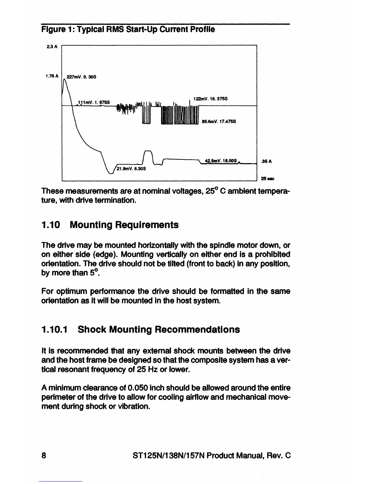
Figure 1 : Typical
RMS
Start-Up Current Profile
2.3A
~---------------------.
1.76A 227mV.0.30S
85.6mV. 17..475$
42.SmV.
18.00S
.35
A
21.9mV.
6.30S
'---------------------'~-
These measurements
are
at nominal
voltages,
25° C ambient tempera-
ture, with drive termination.
1.10 Mounting Requirements
The drive
may
be
mounted horizontally
with
the
spindle motor
down,
or
on
either side
(edge).
Mounting
vertically
on
either
end
is a prohibited
orientation.
The
drive should not
be
tilted (front to
back)
In
any
position,
by
more
than
5°.
For optimum performance the drive
should
be
formatted
In
the
same
orientation
as
It will
be
mounted
In
the host
system.
1.10.1 Shock Mounting Recommendations
It
Is
recommended
that
any
external shock
mounts
between
the drive
and
the host frame
be
designed
so
that the composite system
has
aver-
tical
resonant frequency
of
25
Hz
or
lower.
A
minimum
clearance
of
0.050
inch
should
be
allowed
around the entire
perimeter of the drive to allow for cooling airflow
and
mechanical
move-
ment during shock or vibration.
8 ST125N/138N/157N Product
Manual,
Rev.
C