7
Servo arm.
Adjustable servo
connector.
Loctite secure.
rottle servo arm.
Elevator servo arm.
Rudder servo arm.
Trim and cut.
.
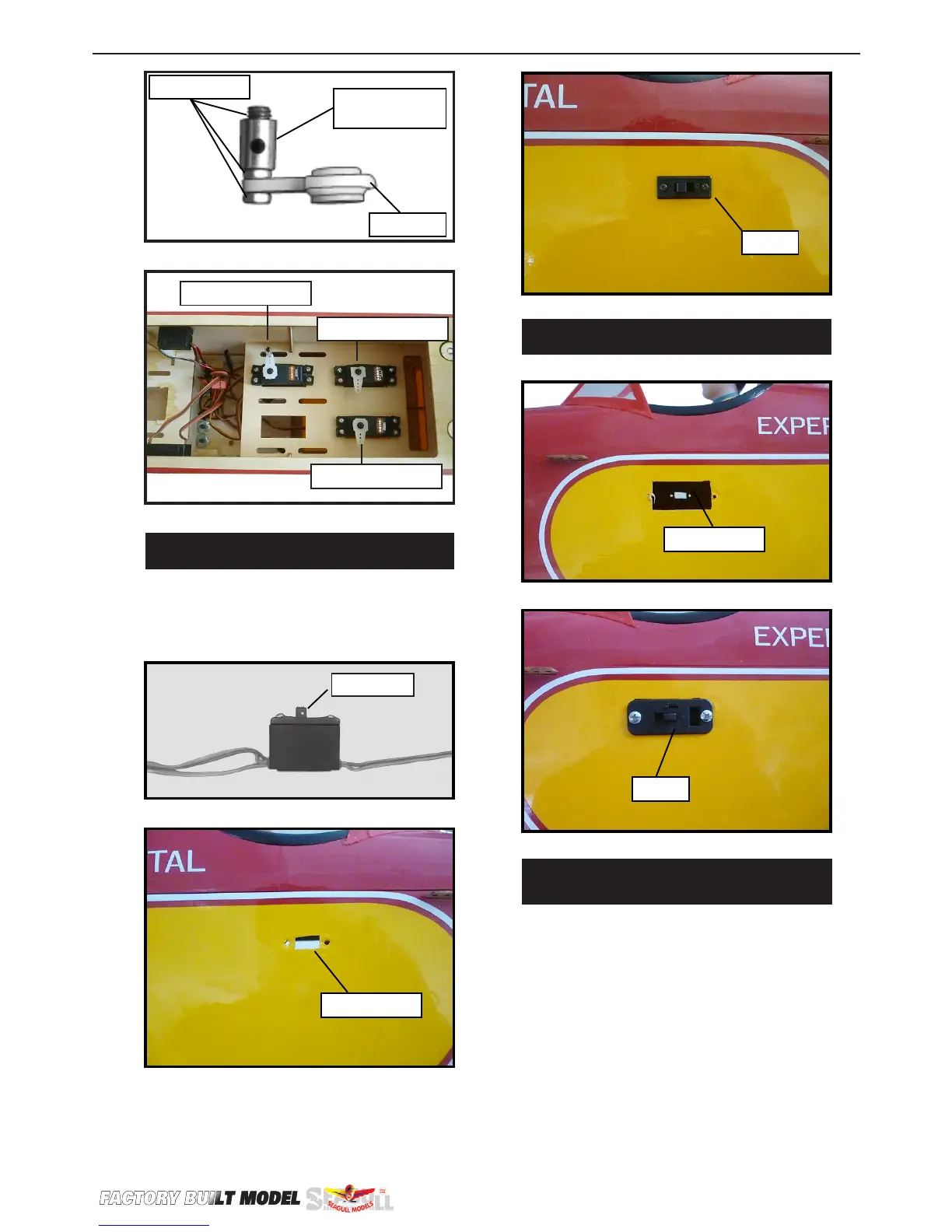
Switch.
INSTALLING THE ENGINE SWITCH.
Trim and cut.
INSTALLING THE RECEIVER SWITCH.
Install the switch into the precut hole in
the side, in the fuselage.
3/32” Hole.
Switch.
INSTALLING THE STOPPER
ASSEMBLY.
1) Using a modeling knife, carefully cut
o the rear portion of one of the 3 nylon
tubes leaving 1/2” protruding from the
rear of the stopper. is will be the fuel
pick up tube.
2) Using a modeling knife, cut one length
of silicon fuel line. Connect one end of
the line to the weighted fuel pick up and
the other end to the nylon pick up tube.