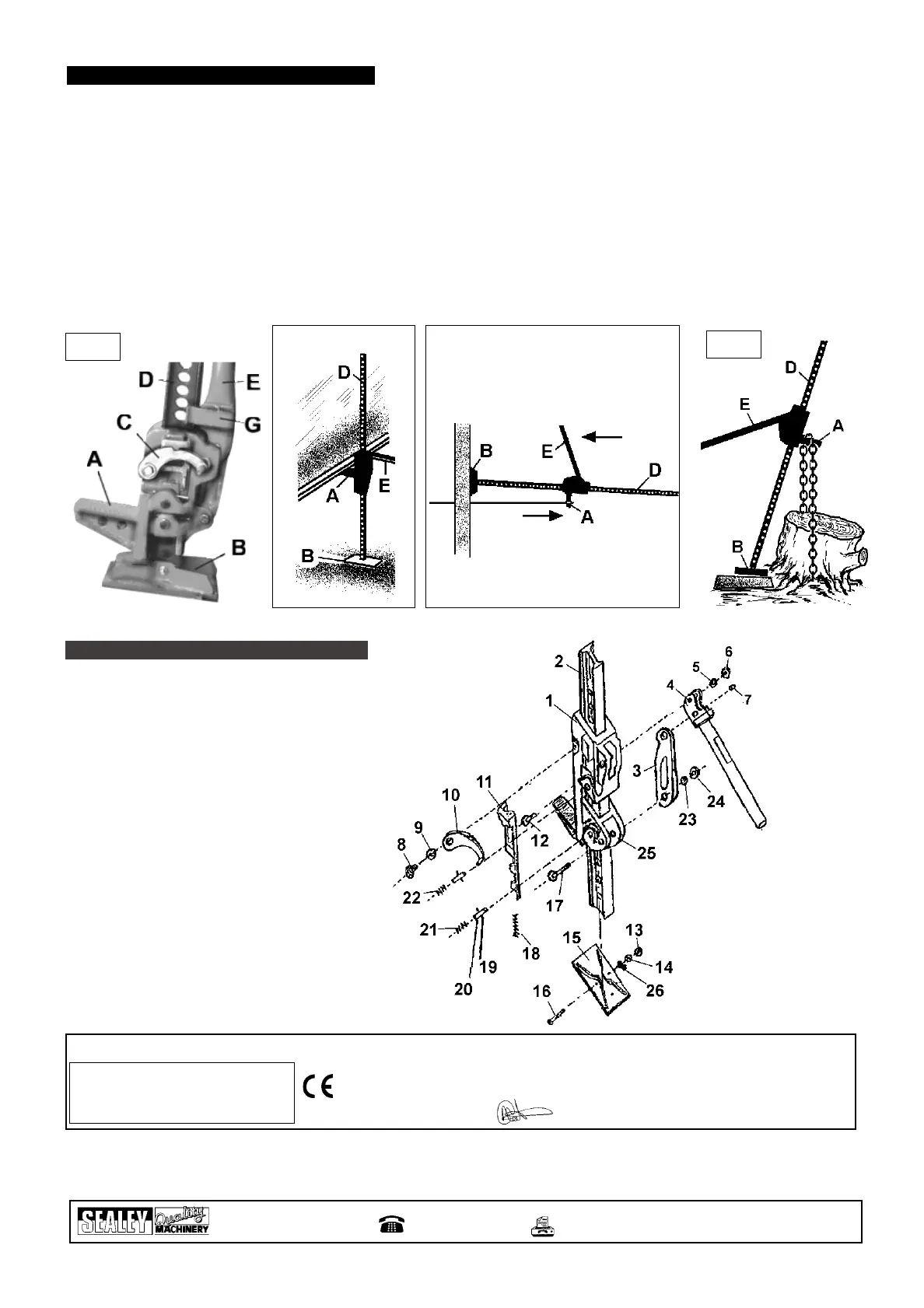
4. PARTS LIST
1 FJ48/01 LARGE RUNNER
2 FJ48/02 STEEL BAR
3 FJ48/03 CONNECTING ROD
4 FJ48/04 ROCKER
5 FJ48/05 WASHER
6 FJ48/06 NUT
7 FJ48/07 PIN
8 FJ48/08 SCREW
9 FJ48/09 WASHER
10 FJ48/10 REVERSING LATCH
11 FJ48/11 REVERSING SWITCH
12 FJ48/12 SCREW BOLT
13 FJ48/13 NUT
14 FJ48/14 WASHER
15 FJ48/15 BASE
16 FJ48/16 SCREW BOLT
17 FJ48/17 SCREW BOLT
18 FJ48/18 SPRING
19 FJ48/19 PIN
20 FJ48/20 REVERSE ROD
21 FJ48/21 SPRING
22 FJ48/22 SPRING
23 FJ48/23 WASHER
24 FJ48/24 NUT
25 FJ48/25 SMALL RUNNER
26 FJ48/26 SPRING LOCK WASHER
Declaration of Conformity We, the sole importer into the UK, declare that the product listed below is in conformity with the following EEC standards and directives
Farm Jack Model FJ48
98/37/EC Machinery Directive
(S.I. 1992/3073 & Amendments).
15th June 2000
Signed by Mark Sweetman
The construction file for this product is held by the Manufacturer and may be inspected, by a national authority, upon
request to Jack Sealey Ltd.
For Jack Sealey Ltd.
Sole importer into the UK
of Sealey Quality Machinery
Sole UK Distributor
Sealey Group,
Bury St. Edmunds, Suffolk.
01284 757500
E-mail: sales@sealey.co.uk
01284 703534
NOTE: It is our policy to continually improve products and as such we reserve the right to alter data, specifications and component parts without prior notice.
IMPORTANT: No liability is accepted for incorrect use of product. WARRANTY: Guarantee is 12 months from purchase date, proof of which will be required
for any claim. INFORMATION: For a copy of our latest catalogue and promotions call us on 01284 757525 and leave your full name and address, including postcode.
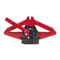
3.1. GENERAL LIFTING p WARNING! Before lifting ensure Section 1 safety instructions are read and understood.
3.1.1. Position jack foot (all figures below item B) on a stable, strong base and locate lifting beak (A) appropriately in order to take the strain.
3.1.2. Pull the direction latch (fig 1.C) up until it clicks into place.
3.1.3. Hold the beam (D) steady and pull the operating handle (E) downward, (or forward if used horizontally fig 3).
3.1.4. Continue to pump the handle. You will feel resistance on the downward (or forward) stroke.
3.1.5. When the load is lifted to the required height, (or correct strain has been applied), set the handle in the upright position (or parallel
to the beam (D) and engage clip (fig 1.G) onto the beam.
3.1.6. Place a 1/2 steel bolt (not supplied) through the hole immediately below the lifting mechanism to act as a safety pin.
p WARNING! The jack is for lifting or pulling, and must not be used to support a load. Use appropriate supports for a load.
3.1.7. To lower a load, (or release the strain), push the direction latch (fig1.C) down. Pump the handle (the load must be a minimum of 50kg
To correctly activate the lowering mechanism). When lowering, you will feel resistance on the upward (or backward) stroke of handle.
3.1.8. When not in use, keep the jack clean and well lubricated.
3. OPERATING INSTRUCTIONS
fig 1
fig 2
fig 3
fig 4
FJ48 - 0016 - (1) - 150600
 Loading...