iMAG 4700 INSTRUCTIONS
Seametrics • 253.872.0284 Page 11 seametrics.com
CONNECTIONS
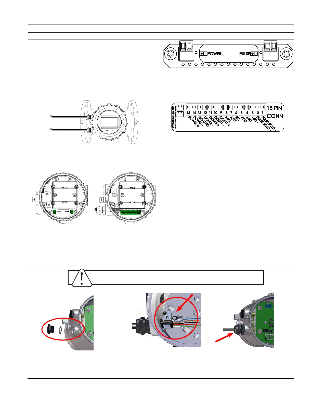
Cable Gland Opening and Sealing
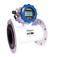
15 Pin Connector for iMAG 4700 DC Versions
Two 2-pin Connectors for iMAG 4700 Battery Version
General Cable Information
In the iMAG 4700 meter, there are a maximum of two
Power/Output cables that can be installed. These cables
contain the wires for DC power and for any output (scaled
pulse, 4-20mA, Modbus
®
, HART, and high speed digital).
(See Sample Cable Wiring Diagrams and Cable Wiring
Table.) It is up to the user to decide how to best organize
the wiring for the application.
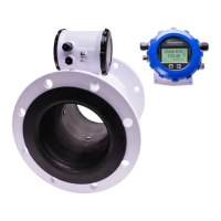
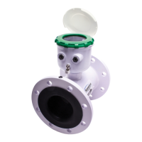
The iMAG 4700 is available in either Battery or external DC
versions.
Power/Output Cable 2
Power/Output Cable 1
Integrated
Meter
Battery version with two
2-pin connectors
DC version with a 15-pin
connector. (Your meter
may have one or two
cable glands, depending
on conguration.)
WARNING: Improper sealing of glands or cables will invalidate any warranty.
Remove plug & o-ring. Insert
cable gland/strain relief. Feed
cable through cable gland.
CRITICAL!
Torque cable gland sealing
nut to 22 in-lbs.
Clamp cable with strain relief
clips. Attach drain wire lug to
bracket post.
 Loading...