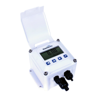
iMAG 4700 INSTRUCTIONS
Seametrics • 253.872.0284 Page 9 seametrics.com
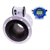
Positioning the Meter
These meters can be installed horizontally, vertically (with
upward ow), or in any radial position. Using a check
valve on the upstream side of the meter, and/or an air
vent (vacuum relief valve) in the same, unobstructed
run of pipe as the meter, is required in any installation
where the meter may be exposed to suction when the
system is not in normal operation. Suction can cause
damage to the liner. Liner damage caused by suction,
without the use of a check valve and/or air vent, may
void the warranty.
Straight Pipe Recommendations. The iMAG requires
straight pipe before and after the meter for best accuracy.
However, the ability of electromagnetic meters to average
the ow across the entire pipe allows for shorter straight
pipe recommendations than most mechanical meters (see
page 7).
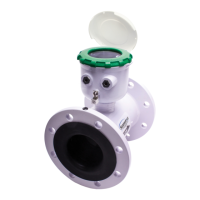
Full Pipe Recommendations. To prevent false readings,
this meter is designed to indicate ‘EMPTY PIPE’ if one or
more electrodes is exposed. For highest accuracy, install the
meter so that the pipe will be full when there is ow. If air
bubbles may be present in the pipe or sludge accumulation
is an issue, rotate the meter by one ange hole to position
the control housing at a 45˚ angle (see diagrams on page
8).
Fittings. The iMAG has ANSI 150 lb. drilled anges and
will mate with any other ANSI 150 lb. anges. See table on
page 10 for ange bolt tightening torque specications.
Calibration. The iMAG is factory-calibrated and will not
require any form of eld calibration.
Chemical Injection. When the iMAG is used in a chemical
injection application, the chemical injection point must be
placed downstream of the magmeter OR far enough
upstream for complete mixing to occur before the uid
reaches the meter. When unmixed chemical alternates with
water passing through the meter, the rapid changes in
conductivity may cause sudden spikes and drops in the
meter’s reading, resulting in inaccurate measurement. The
magmeter will re-stabilize, however, with a steady ow of
uid of uniform conductivity.
CAUTION: These ow sensors are not
recommended where installation may
expose the ow sensor to boiler pressure
and temperature. Maximum recommended
operating temperature is 130˚ F.
CAUTION: In chemical injection applications,
install chemical injection point downstream
of magmeter, or far enough upstream to
allow complete mixing of uids.
INSTALLATION
Installing Gaskets
1. Select a suitable full-face gasket.
• Only use at compressible gaskets (either pliable
or hard ber will work).
• Use a material compatible with the uid you will
be using.
• Thickness should be 1/8” - 1/4” (3 - 6 mm),
depending on the atness of the pipe ange
surface.
• Inner diameter must be larger than opening in
ow meter.
2. Be sure all mating surfaces are smooth and free of
debris.
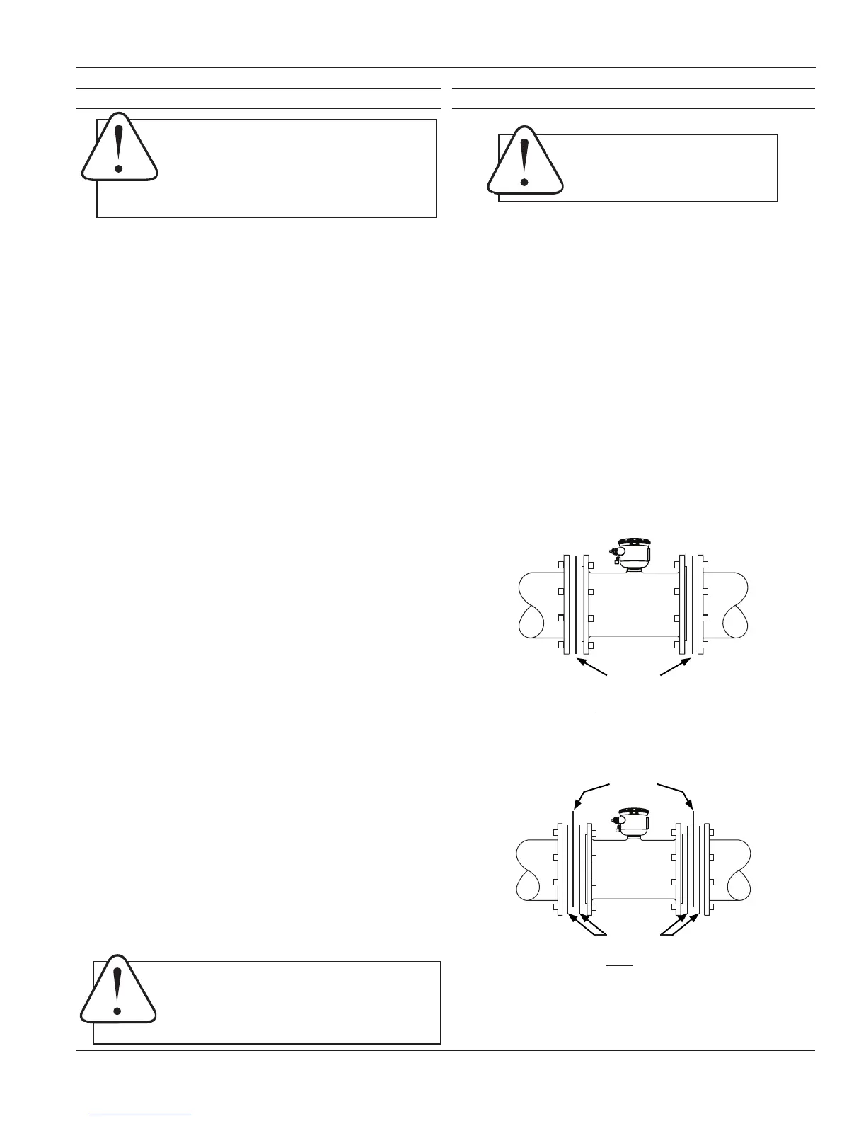
3. Install gaskets on each end of meter as shown in
diagrams below. If using grounding rings, install
one gasket on each side of the grounding ring.
Installation without grounding rings
Installation with grounding rings
GASKETS
Gaskets are required at all
junctions.
Gaskets
Gaskets
Grounding
Rings
 Loading...