UNPACKING AND CH
CONTENTS
WARRANTY .... : ................................ 2
General Safety Instruction for Power Tools .......... 2
Additional Safety Instructions for Wood Shaper ...... 3
Motor Specifications and Electrical Requirements .... 4
UNPACKING AND CHECKING CONTENTS ....... 5
List of Loose Parts .............................. 5
ASSEMBLY ...................................... 6
Tools Needed ................................... 6
Installing Elevating Rod and Table Support ........ 7
Mounting Belt Guard and Motor to Motor Mount .. 7
Installing Motor Pulley ........................... 8
Mounting Motor Support Assembly to Shaper ..... 9
Mounting Switch Assembly ...................... 9
Assembling Steel Legs .......................... 9
Mounting Wood Shaper on Floor Stared .......... 10
Plugging in Motor .............................. 10
Installing Shaper Fence -- For Straight Edge
Shaping only ................................. 11
installing Shaper Cutter Guard --- For Curved
or Irregular Shaping only ..................... 11
GETTING TO KNOW YOUR: WOOD SHAPER .... 12
On-Off Switch ................................. 12
Elevating Control Lever ......................... 13
Spindle Lock Knob ............................. !3
Spindle ........................................ t3
Spacers ....................................... t 3
Keyed Washer ................................. 13
Fence Adjusting Knob .......................... 13
Fence Lock Knob ............................... t3
Fence Faces ................................... t3
Cutter Guard ................................... 13
Starting Pin .................................... 13
Removing and Installing Cutter .................. 13
ADJUSTMENTS ................................ 14
Shaper Fence .................................. !4
Fence Faces ................................... 14
BASIC SHAPING OPERATIONS ................. 15
Use of Cutter Spacers .......................... t5
Straight Edge Shaping .......................... 16
Shaping With Use of Miter Gauge and
Hold-Down Clamp (Optional Accessory) ........ 16
Irregular or curved Shaping ..................... 17
MAINTENANCE ................................. 19
LUBRICATION .................................. 19
Motor Maintenance and Lubrication ............. t9
RECOMMENDED ACCESSORIES ............... 19
TROUBLE SHOOTING ........................... 20
REPAIR PARTS ................................. 22
Motor Connections ............................. 27
O
ECKING CO NTENTS
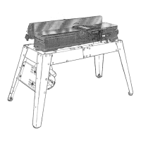
Model 113.239390 Wood Shaper is shipped complete in
one carton and includes st:eel legs and motor.
Model 113.239201 Wood Shaper is shipped complete in
one carton but DOES NOT INCLUDE Steel Legs or Motor.
Separate al! parts from p_oking materials and check each
one with the illustration and the tist of Loose Parts to make
certain all items are accounted for, before discarding any
packing material.
If any parts are missing, do not attempt to assemble the
Shaper, plug in the pov_er cord or turn the switch on until
the missing parts are obtair_ed and are installed correctly.
Remove the protective oil that is applied to the table top
and edges of the t_ble. Use any ordinary household type
grease and spot remover.
CAUTION: Never use g,asoline, naptha or similar highly
volatile solvents.
Apply a coat of automobilJe wax to the table.
Wipe aH parts thoroughly with a clean, dry cloth,
WARNING: FOR yOUR OWN SAFETY, NEVER
CONNECT PLUG TO POWER SOURCE OUTLET UNTIL
ALL ASSEMBLY STEPS ARE COMPLETE, AND YOU
HAVE READ AND UNDERSTAND THE SAFETY AND
OPERATIONAL INSTR UCT_ONS.
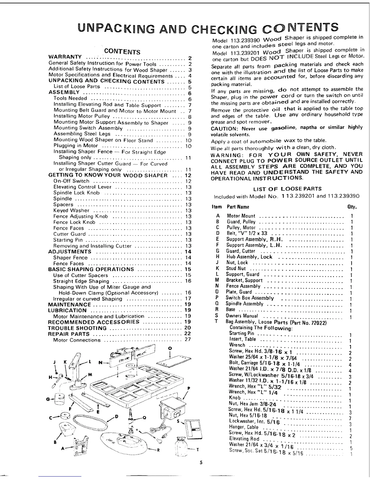
LIST OF LOOSE PARTS
Included with Model No. 113.23920t and 113,239390
Item Part Name Qt_/.
A
B
C
D
E
F
G
H
J
K
L
M
N
O
P
Q
R
S
T
Motor Mount .............................
Guard, Pulley ............................. t
Pulley, Motor ............................. 1
Belt, "V" 1/2 x 33: ........................... 1
Support A_sembfy, _H ..................... 1
Support Assembly, L.H ...................... 1
Guard, Cutter ............................. t
Hub Assembly, Lock ....................... t
Nut, Lock ............................... 1
Stud Nut .................................. 1
Support, Guard ............................ 1
Bracket, Support ........................... I
Fence Assembly ............................ 1
Plate, Guard ................................ I
Switch Box Assembly ...................... 1
Spin_fe Assembly .......................... 1
Base
Owners Manual
............................ I
Bag Assembly, Loose Parts (Part No. 72022)
Containing The Fo_llowing:
Starting Pin 1
Insert, Table
............................ I
Wre rich 1
Screw, Hex Hd. 3/8-16; x 1 2
=====================2
Bolt, Carriage 5/t6-18 × t-1/4 .............. 4
Washer 21164 i.D. x 71B O.D. x 1/8 .......... 4
Screw, W/L0ckv_asher 5716-18 x 3/4 ......... 3
Washer 11/32 I.D. x 1- !/16 x 1,/8 ............ 2
Wrench, Hex "L °' 5132
...... * ............. 1
Wrench, Hex *'L'" I/4
Knob
3
Nut, He× 5/16-t8
L0ckwasher, Int. 5I:t _;................ 7
Han_er, Cable - ..................... 3
Screw0 Hex H_1."5"1:I_: lj'_ 1"2 .............. 1
Elevating Rod ................ 2
 Loading...