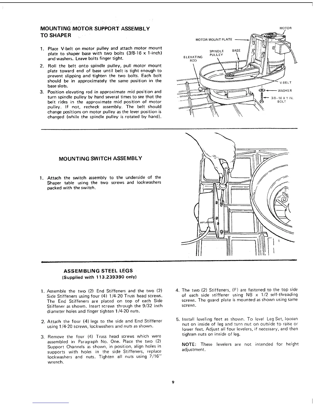
MOUNTING MOTOR SUPPORT ASSEMBLY
TO SHAPER
1. Place V-belt on motor pulley and attach motor mount
plate to shaper base with two bolts (3/8-16 x 1-inch)
and washers. Leave bolts finger tight.
2. Roll the belt onto spindle pulley, pull motor mount
plate toward end of base until belt is tight enough to
prevent slipping and tighten the two bolts. Each bolt
should be in approximately the same position in the
base slots.
3o Position elevating rod in approximate mid position and
turn spindle pulley by hand several times to see that the
belt rides in the approximate mid position of motor
pulley. If not, recheck assembly. The belt should
change positions on motor pulley as the lever position is
changed (while the spindle pulley is rotated by hand).
ELEVATING
ROD
MOTOR MOUNT PLATE
SPINDLE BASE
PULLEY
MOTO R
1.
2.
3,
MOUNTING SWITCH ASSEMBLY
Attach the switch assembly to the underside of the
Shaper table using the two screws and Iockwashers
packed with the switch.
ASSEMBLING STEEL LEGS
(Supplied with 113,239390 only)
Assemble the two (2) End Stiffeners and the two (2)
Side Stiffeners using four (4) 1/4_20 Truss head screws.
The End Stiffeners are placed on top of each Side
Stiffener as shown. Insert screws through the 9/32 inch
diameter holes and finger tighten 1/4-20 nuts.
Attach the four (4) legs to the side and End Stiffener
using 1/4-20 screws, _ockwashers and nuts as shown.
Remove the four (4) Truss head screws which were
assembled in Paragraph No. One. Place the two (2)
Support Channels as shown, in position, align holes in
supports with holes in the side Stiffeners, replace
tockwashers and nuts. Tighten all nuts using 7/16"
wrench,
4. The two (2) Stiffeners, (F) are fastened to the top side
of each side stiffener using N8 x t/2 self-threading
screws. The guard plate is mounted as shown using same
screws.
5. Install leveling feet as shown. To ieve! Leg Set, ]oosen
nut on inside of leg and turn nut on outside to raise or
lower feet. Adjust a_l four levelers, if necessary, and then
tighten nuts on inside of leg.
NOTE: These levelers are not intended for height
adjustment.
 Loading...