Calibrationensuresthebuildplateisexactlyperpendiculartothe
printnozzle,andthatitsmovementscomplywithcommands
fromthe3DCreate&Printsoftware.Youshouldonlyneedto
calibratetheprinteronce(i.e.aspartofthisinitialsetup).
Youwillneedthecalibrationgaugesupplied.Youwillalsoneed
tooperatetheprinterwiththehoodraised;toenablethis,goto
Cong,selectPrinterSettings,andchecktheboxmarkedDisable
HoodSafetySwitch.Youmayalsoprefertoremovetheprint
guard(seestep8,page6)foreasieraccesstothenozzle.
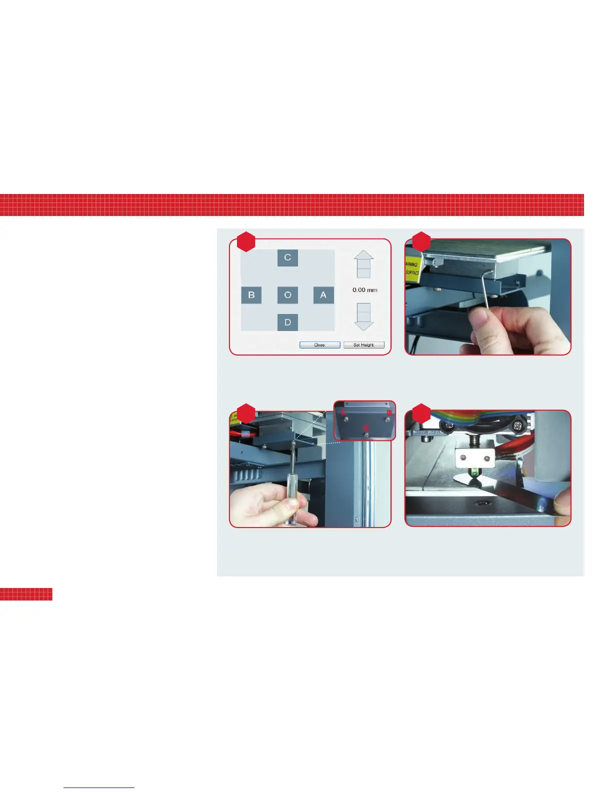
1. The Calibration Setup (image A, right) appears when you first try
to connect the software to the printer. The five points O, A, B, C,
D correspond to the areas on the build plate where you will be
checking the gap between the plate and the print nozzle. Click
on each point in turn to move the plate accordingly.
2. Click on the ‘up’ arrow to raise the build plate. For 10mm travel,
click the arrow head. For 1mm travel, click the centre part of the
arrow. For 0.1mm travel, click the arrow base. Raise the plate by
a total of 110–115mm, taking it to 10–15mm below the nozzle.
3. Now click through the ve squares and watch the plate as it
tracks beneath the nozzle. If it looks level, raise it to within 2mm
of the nozzle, then go to step 6. Alternatively, if the plate is on a
tilt – however slight – continue to step 4.
4. With the small Allen key, loosen (DO NOT remove) the three
grubscrews in the plate support base (image B). This will allow
you to adjust the vertical bolts that control the tilt of the plate.
5. Track from square to square again (image A) and check the gap.
Using a screwdriver or your fingers, turn the vertical adjustment
bolts (image C) until you achieve a consistent gap between plate
and nozzle at all five squares. This may take a while; you should
make only small adjustments to each bolt in turn.
6. Bring the plate up to <1mm below the nozzle. Adjust the elevation
until the calibration gauge just slides into the gap (image D).
Retighten grubscrews (image B) and check again with the gauge.
7. Finally, click Set Height. Your machine is now calibrated.
8
4. calibrating your printer
VISIT www.3dprinter-collection.com TO DOWNLOAD AND INSTALL THE SOFTWARE
IntheCalibrationSetupwindow,usetheupanddown
arrowstoraiseorlowerthebuildplate.Eachthree-part
arrowenablesyoutoadjusttheplateheightingraded
increments(10mm,1mm,or0.1mm).
Now,carefullyturntheadjustmentboltstoleveltheplate.For
instance,tolowertheright-handside,tightentheright-hand
bolt(markedRabove).Toraiseit,loosenboltR.Toraisethe
backoftheplate,loosenthecentreboltC;andsoon.
Toadjustthetiltofthebuildplate,rstusethesmallAllen
keytoloosenthethreegrubscrews(twoinfront,one
behind)thatlocktheverticaladjustmentbolts.DONOTfully
extractthegrubscrews,astheyaretinyandeasytomisplace.
Onceyouhavereducedthegapbetweenbuildplateand
nozzletoamillimetreorless,usethecalibrationgaugeto
measureit.Thegaugeshouldjustslideintothegapatall
vepointsoftheCalibrationSetupwindow(imageA).
calibration
DOWN
UP
a b
c d
L
C
R
 Loading...