26
© Seemix Sound AS
4. Options
4.1 Insert Points on Inputs, INS3800
Insert points on inputs is available as an option for any or all channels. The insert
points appear on 9-pin D-sub connectors which extend over the top of the back panel
above each module. Both inputs and outputs are unbalanced. Pin-outs and dimen-
sions are given in section 5.5
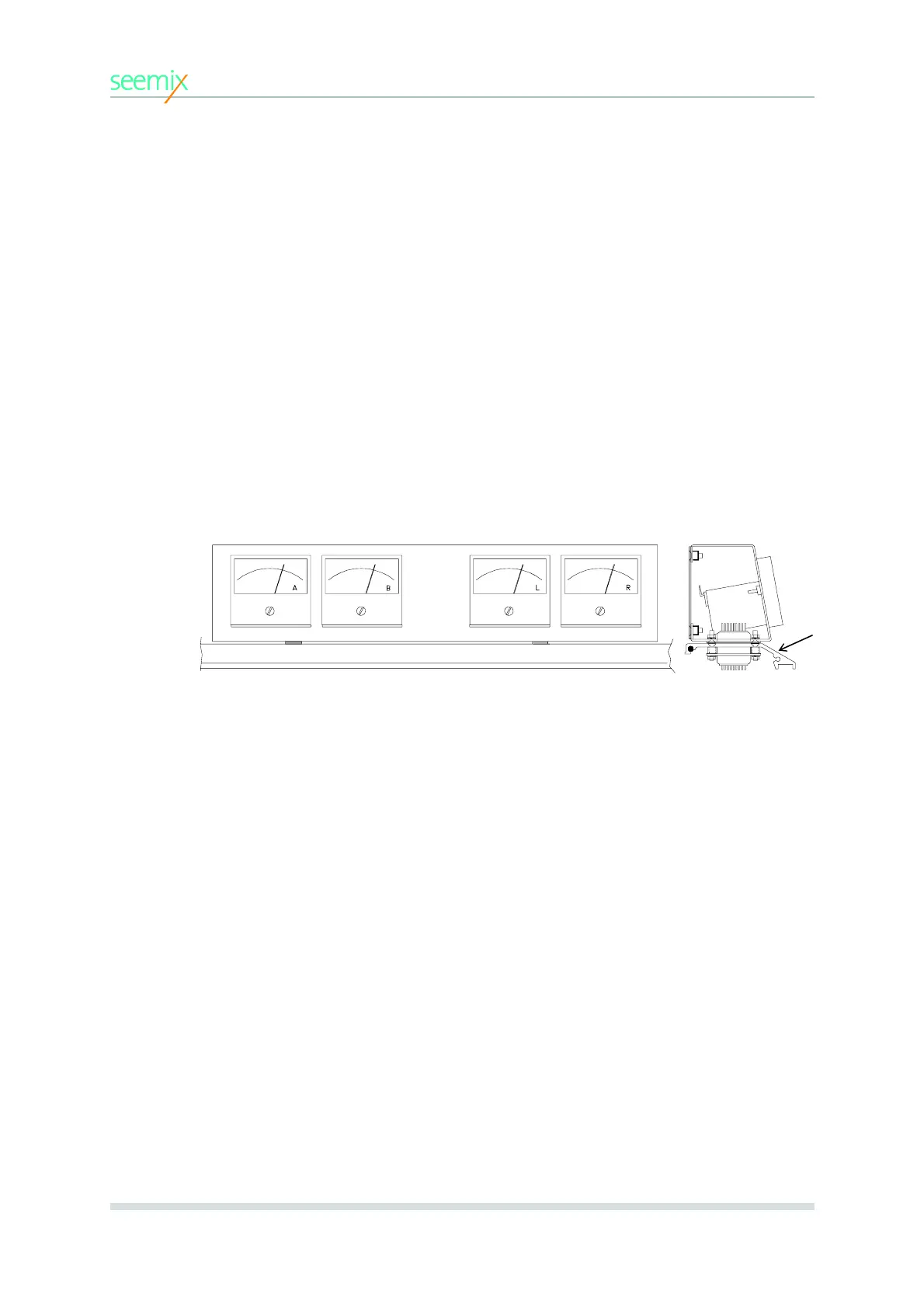
4.2 VU Meter Bridge, VU3800
A meter bridge housing 4 analogue VU meters for A + B outputs and L + R monitor
outputs (shown below) is available as an option.
4.3 Expansion Cable, EC3800
An expansion cable for connecting two Seeport mixers together in a master/slave
configuration is available. The expansion connectors on the mixers are 25-pin D-sub.
Pin outs for the connections are given in section 5.5.
4.4 Transparent Dust Cover, DC3808/12/16
A transparent plastic dust cover is available for all frame sizes. This functions as a
protection to the user surface and guards against unintended contact with the mixer
controls when on air.
4. Options
4.1 Insert Points on Inputs, INS3800
Insert points on inputs is available as an option for any or all channels. The insert
points appear on 9-pin D-sub connectors which extend over the top of the back panel
above each module. Both inputs and outputs are unbalanced. Pin-outs and dimen-
sions are given in section 5.5
4.2 VU Meter Bridge, VU3800
A meter bridge housing 6 analogue VU meters for A, B, C and D outputs plus L and
R monitor outputs (shown below) is available as an option. The bridge is connected
via two 9-pin D-sub connectors positioned on the mixer’s top panel.
4.3 Expansion Cable, EC3800
An expansion cable for connecting two Seeport mixers together in a master/slave
configuration is available. The expansion connectors on the mixers are 25-pin D-sub.
Pin outs for the connections are given in section 5.5.
4.4 Transparent Dust Covers, DC3808/12/16
A transparent plastic dust cover is available for all frame sizes. This functions as a
protection to the user surface and guards against unintended contact with the mixer
controls when on air.
4. OPTIONS
front view
side view
(not drawn to scale)
top of mixer