Do you have a question about the Seg SP740 Series and is the answer not in the manual?
Provides essential guidelines for effective and correct use of the product.
Details safety instructions for operating in hazardous zones and maintaining intrinsic safety.
Lists applicable certifications and standards for the positioner.
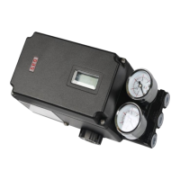
Details key features, optional modules, labels, and product coding.
Covers detailed technical data, performance metrics, and specifications.
Explains how the positioner works and describes its internal components.
Details intrinsic safety explosion proof regulations and barrier specifications.
Provides dimensional drawings and specifications for the SP740 Standard Type.
Provides dimensional drawings and specifications for the SP740 Lever Type.
Provides dimensional drawings and specifications for the SP740 Fork Lever Type.
Provides dimensional drawings and specifications for the SP740 Namur Type.
Covers cautions before installation and lists necessary tools.
Detailed instructions for installing the linear positioner, including cautions.
Guidance on installing rotary positioners, including bracket assembly and steps.
Specifies requirements for air supply pressure and filter regulator settings.
Details piping connections for single and double acting actuators.
Highlights safety measures for power connection and general electrical precautions.
Explains terminal connections, limit switch terminals, intrinsic safety wiring, and grounding.
Describes how to adjust the operation location of mechanical limit switches.
Lists available PCB board types for position transmitter and HART communication options.
Provides warnings before calibration and describes the function of the positioner's buttons.
Explains the RUN mode, including displayed values and their meanings.
Details the steps for AUTO CAL, AUTO PV, and AUTO ALL calibration methods.
Guides through Manual mode and parameter adjustments like Dead-Zone, KP-UP, KP-DOWN.
Explains SV NORM, DP NORM, and FB NORM modes for hand calibration adjustments.
Covers valve operation modes: ACT DA/RA, Flow Characterization, and Tight Shut settings.
Describes how to use View mode to check positioner information and status.
Lists common error codes, their causes, and recommended actions for resolution.
Explains warning codes indicating potential abnormal operation or degraded precision.
Illustrates the LCD operation flow and navigation path for various functions.
| Type | Electro-pneumatic |
|---|---|
| Supply pressure | 1.4 to 7 bar (20 to 100 psi) |
| Input signal | 4 to 20 mA |
| Protection class | IP66 |
| Ambient Temperature | -40 to 85 °C (-40 to 185 °F) |
| Housing Material | Aluminum |
| Certification | ATEX, IECEx |