22
www.seuservice.com
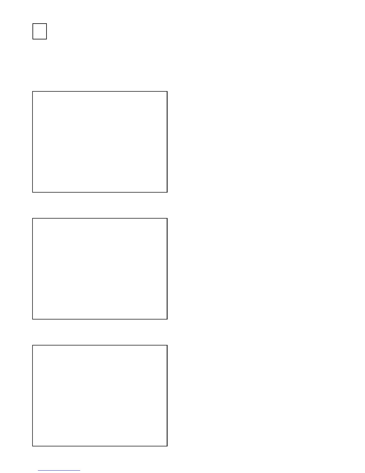
RAM TEST
IC29 GOOD
IC35 GOOD
IC16 GOOD IC18 GOOD
IC20 GOOD IC22 GOOD
IC09 GOOD IC10 GOOD
IC11 GOOD IC12 GOOD
PRESS TEST BUTTON TO EXIT
Å° INPUT TEST Å°
- SYSTEM SWITCH -
CHUTE #1 OFF CHUTE #2 OFF
TEST OFF B TEST OFF
SERVICE OFF B SERVICE OFF
- GAME SWITCH -
START OFF
SC OFF TC OFF
ABS OFF IBS OFF
- WING SHIFT -
WING L ON WING R OFF
- ANALOG DEVICE -
HANDLE 7B H ACCEL 2E H
BRAKE 2F H
- OTHER DEVICE -
VISUAL MEMORY UNCONNECTED
PRESS SERVICE + TEST BUTTON TO EXIT
Å° OUTPUT TEST MENU Å°
LAMP TEST
DRIVE BOARD TEST
-> EXIT TO SYSTEM TEST MODE
SELECT WITH SERVICE BUTTON
AND PRESS TEST BUTTON
(3) OUTPUT TEST
(2) INPUT TEST
In the TEST MODE, ascertain that the assembly has been made correctly and IC BD. is
satisfactory (refer to Section 9).
In the test mode, perform the following test:
ASSEMBLING CHECK
(1) MEMORY TEST
Selecting the RAM TEST on the system test mode
menu screen causes the on-board memory to be tested
automatically. The game board is satisfactory if the
display beside each IC No. shows GOOD.
Selecting the INPUT TEST on the game test mode
menu screen causes the screen (on which each switch
and V.R. are tested) to be displayed. Press each
switch. For the coin switch test, insert a coin from the
coin inlet with the coin chute door open. If the
display beside each switch indicates "ON," the switch
and wiring connections are satisfactory.
Check the display of V. R. value for the steering
wheel and accelerator & brake. If the V. R. values are
not satisfactory, refer to Sections 10 & 11.
The OUTPUT TEST menu screen in the game test
mode allows Lamp and Motor to be checked. Check
if Lamp and Motor are satisfactory.