5
Date Code 20200324 SEL Application Guide 2020-05
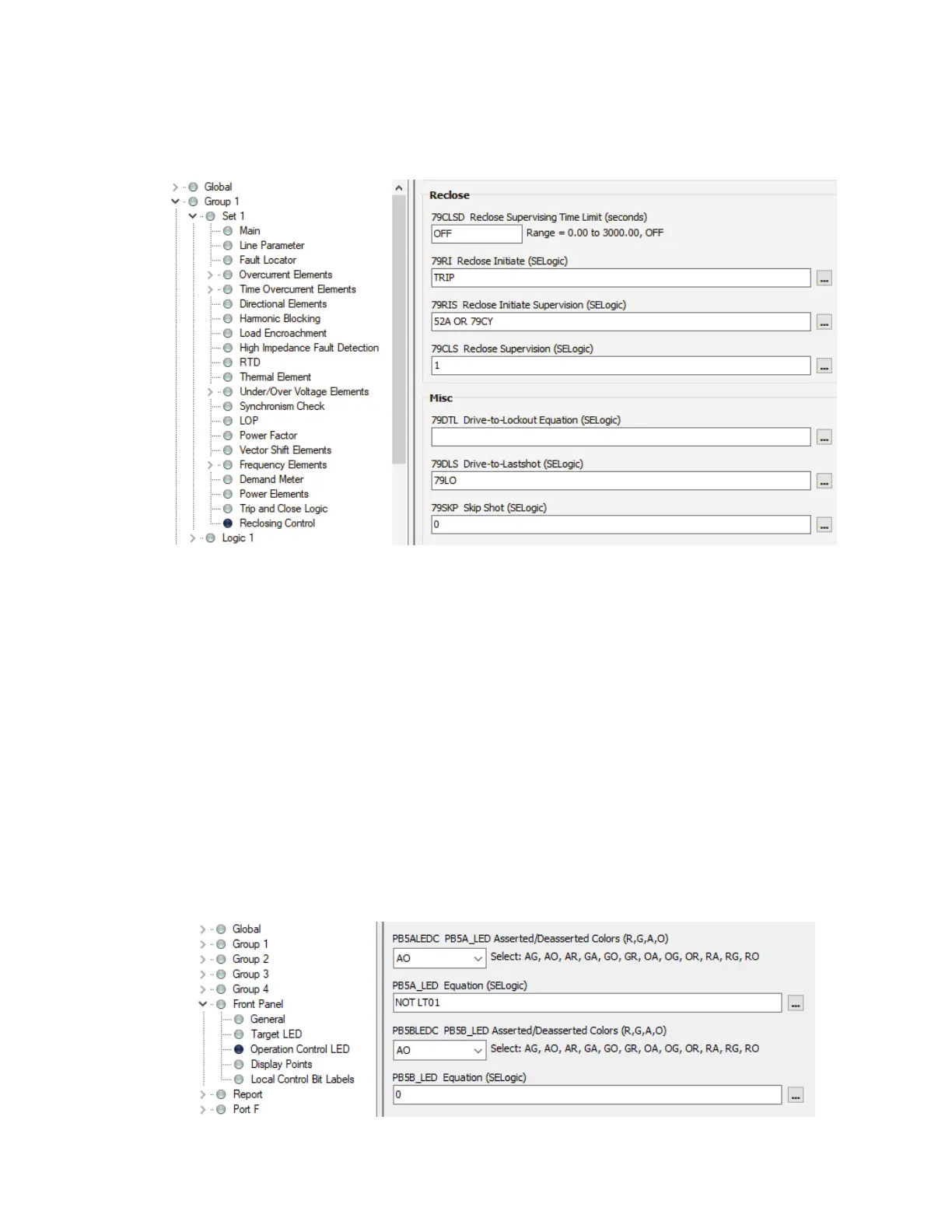
For models ordered with the reclosing option, in addition to modifying the close equation, use the
latch bit to disable reclosing by adding NOT LT01 in the 79DTL drive-to-lockout equation, as
shown in Figure 7.
TURN ON OR FLASH PUSHBUTTON LED DURING MAINTENANCE MODE
Now we are going to turn on or flash a pushbutton LED when maintenance mode is active.
Turn On LED
Every operator control pushbutton has two LEDs. The PBnA_LED setting governs the top LED,
and the PBnB_LED setting governs the bottom LED (n indicates the pushbutton number). To turn
on the top LED during maintenance mode, set the PB5A_LED setting equal to NOT LT01, as
shown in Figure 8. Disable the bottom LED by setting PB5B_LED equal to 0. The color of the top
LED is dictated by the PBnALEDC setting, and the color of the bottom LED is dictated by the
PBnBLEDC setting. In this example, we set PB5ALEDC = AO. This means that when the
PB5A_LED equation evaluates to logical 1, the LED turns on with an amber color (A for amber).
On the other hand, when PB5A_LED evaluates to logical 0, the LED turns off (O = OFF). The
color of the bottom LED does not matter because it is not being used.
Figure 7 Logic to Disable Reclosing During Maintenance Mode
(...) OR NOT LT01
Figure 8 Logic to Turn On Pushbutton LED During Maintenance Mode