10
E
F
F
E
11-1/2" (292mm)
12-3/4" (324mm)
14" (356mm)
14-1/2" (369mm)
15-3/4" (400mm)
17" (432mm)
10-5/8" (270mm)
11-7/8" (302mm)
13-1/8" (334mm)
6"
7"
8"
F
WALL SUPPORT (WSP)
To complete a proper Wall Support installation, the following parts
may be required:
- Wall Support Package: - Intended for a through-the-wall installa-
tion where the chimney has a lateral connection.
- Adjustable Roof Flashing: - Required when the chimney
penetrates a roof or a roof overhang.
- Insulated Tee: - Required when the chimney is installed through
and along a vertical wall either on the exterior or interior.
- Wall Bands: - Required to provide lateral support to the chimney.
- Suitable lengths of chimney: - The chimney diameter should be
sized to suit the appliance.
- Interior Wall Plate and Exterior Wall Plate: - Required when going
through a combustible wall.
- Insulated Wall Thimble: - Required to satisfy through-the-wall
installation where framing an opening may not be practical.
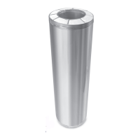
- Round Top: - To exclude rain and/or leaves into the chimney.
The CF Sentinel Adjustable Wall Support will support up to 40 feet
(12.2 m) of chimney, all of which must be above the support.
1. Determine the center line of the lateral connection (horizontal
length through the wall) and frame in your opening to the dimen-
sions specified in Table 3. For a non-combustible wall (concrete
block or poured foundation), cut a hole 1/8" greater than the outside
diameter of the chimney as per Table 3. DO NOT PLACE ANY
LOOSE INSULATION around the horizontal chimney length within
the framed opening when using a Wall Plate Spacer or Insulated
Wall Plate Spacer. Maintain the required minimum 2" (50mm) air
space clearance to combustible materials.
2. Assemble braces, brackets and angles to the base plate using 1/
4" nuts and bolts, with braces up or down as necessary (DOWN IF
CHIMNEY GOES THROUGH WALL) as per Figure 19 & 20a and if
it is an interior wall support installation (Figure 20b).
3. Nail brackets and angles to framing temporarily making sure that
the base plate is level (and positioned to allow for the installation
of the wall plates, if the chimney goes through the wall).
TABLE 3
Chimney
Size
Hole
Non Combustible
Framed Opening
Combustible
Framing
For Bracing
A.
Framing for through the wall
Insulated Tee
B.
Framing for Tee facing away
from the wall
6. If the Tee is located on an outdoor wall, place the exterior wall
plate over the horizontal Tee branch, and attach an appropriate
insulated chimney length to the Tee branch. Secure in place with
the supplied locking band. Ensure that the clasp of the locking
band is facing down to prevent any water from collecting in the
locking band if locking band is positioned on the exterior of the wall.
NOTE: Interior or Exterior Plates can be substituted with the
Insulated Wall Thimble. In a combustible wall the opening must
be framed in (see Table 3).
Round Top
Storm Collar
Roof Flashing
Wall Plate Spacer
Wall Band
Locking Band
Exterior Wall
Plate (Louvered)
Insulated Tee
Angle Bracket
FIGURE 19
4. Mark, and drill 5/32" pilot holes in the framing for the lag screw
location, or install masonry anchors in proper locations.
5. Remove nails, install lag screws or anchor bolts in all the holes
and tighten all bolts in the assembly.
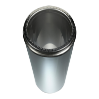
FIGURE 20A
Exterior Wall Support Installation
Base Plate
Bolts
Angle Brace
Wall Bracket
Wall Angle secured to studs
with lag screws
Lag screws
Insulated Tee
Locking Band
Tee Plug with lugs
Exterior Wall Plate (louvered)
Maintain 2"
(50mm)
Min. clearance
Wall Plate Spacer
Locking
Band
9" Pipe Section
Min.
3" (76mm) Min.
39" (990mm) Max.
NOTE: THE CHIMNEY MUST EXTEND AT LEAST
3” (75 MM) INTO THE LIVING SPACE WHERE THE
SMOKE PIPE ADAPTER WILL BE ATTACHED TO THE
CHIMNEY BRANCH.
Locking Band
Smoke Pipe
Adapter
 Loading...