6
Trim Plate
Ceiling
Support
Nailing Holes
3 Nails per Sides
(4 sides)
CEILING SUPPORT (CBSP)
- Suitable lengths of Chimney: - The chimney diameter should be
sized to suit the appliance.
- 15
o
or 30
o
Chimney Elbow: - and suitable supports; resupport
assembly or roof support if required.
- Round Top: - To exclude rain and/or debris into the chim-
ney.
To complete a proper Ceiling Support installation, the following
parts will or may be required:
- Ceiling Support: - Required when supporting chimney with a flat
ceiling.
- Attic Insulation Shield: - Required where a chimney passes into
an unoccupied attic space.
- Firestop Joist Shield: - Required where a chimney passes from
a lower living space into an upper living space or occupied attic
space
- Roof Flashing Assembly: - Required where the chimney
penetrates a roof.
INSTALLATION PROCEDURES:
The CF Sentinel Ceiling Support will support up to 40 feet (12.2m)
of chimney sections, all of which must be installed above the
support. Figures 10 & 11 illustrates the 2 most common types
of Ceiling Support Installation.
Frame (on all 4 sides) a level square opening with the inside
dimensions 14-1/4" (362 mm) square.
With the Lower Bucket removed, place the Ceiling Support
Assembly into the framed opening from below at the ceiling level
(see Figure 7).
The stub end (crimped) of the Smoke Pipe Adapter is intended
to fit inside of the connector pipe from a solid fuel appliance, thus
preventing condensate drips at the chimney connection.
Install inter-connecting stove pipe following appliance
manufactruer's instructions and appropriate building code re-
quirements keeping in mind that the stove pipe run should be as
short and straight as possible and secured in place with a
minimum of 3 sheet metal screws per joint. Generally, for a wood
burning appliance installation, an 18" minimum clearance to
combustibles must be maintained for the stove pipe. NOTE: The
exception to this is a double wall stove pipe, such as Selkirk's
Model DSP which can be installed at reduced clearances to
combustibles. See separate installation instructions for more
details.
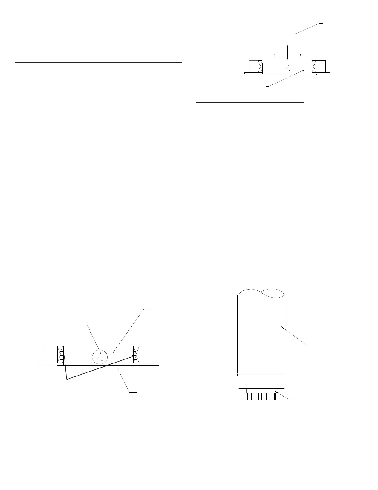
FIGURE 8
SMOKE PIPE ADAPTER (SPA)
FIGURE 7
Basecap w/ Built-In
Smoke Pipe Adapter
Chimney
Length
Finish nailing through all the pre-punched holes (12 nails total)
and fasten the finishing plate onto the ceiling with the 4 supplied
black wood screws. Replace the Lower Bucket into the Ceiling
Support (see Figure 8).
Drive one nail, 1-1/2" common or spiral, part way into each of the
four (4) nailing areas of the support. Check that the trim plate is
level and flush (see Figure 7). You may substitute in lieu of nails
#8 x 1-1/2" wood screws.
Lower Bucket
Insert the Lower
Bucket into the
Ceiling Support
BEFORE LOWERING THE FIRST CHIMNEY LENGTH:
The Basecap Assembly with the short crimped Smoke Pipe
Adapter must be inserted into the female end of the first length
(see Figure 9a).
- Insert the short portion of the short crimped Smoke Pipe Adapter
into the Basecap.
- Ensure the Basecap portion is located on the inside of the
exterior casing of the insulated chimney (flush to the bottom of
the inward bead) and the Smoke Pipe portion is located over the
inner liner of the Chimney Length (see diagram 9b).
FIGURE 9a
Installed Ceiling Support
All openings should be square (all four sides), plumb and in
perfect alignment with each other (see figure 5).
For sloping roofs and/or ceilings, ensure that the framing dimension
is measured in the horizontal plane (see figure 6).