5
AB
6"
14
1
/
4
" x 14/
4
"
362mm x 362mm
8"
7"
14
1
/
2
" x 14
1
/
2
"
369mm x 369mm
14
1
/
2
" x 14
1
/
2
"
369mm x 369mm
14
1
/
4
" x 14/
4
"
362mm x 362mm
14
1
/
4
" x 14/
4
"
362mm x 362mm
15
3
/
4
" x 15
3
/
4
"
400mm x 400mm
15
3
/
4
" x 15
3
/
4
"
400mm x 400mm
17" x 17"
432mm x 432mm
17" x 17"
432mm x 432mm
Web Coupler*
*Not exactly as shown.
Situate the chimney in the structure so that it can be installed
without cutting joists, sills, plates or load bearing partitions or
members.
Connect only one appliance to a chimney.
There should be no draft regulators on solid fuel equipment and
smoke pipe connector.
A minimum smoke pipe connector length of 3 feet (1 m) between
appliance and chimney is recommended.
Your CF Sentinel chimney system is designed for installation
using standard building materials and procedures. The following
tools may be required:
TOOLS
-safety gloves
-safety goggles
-hammer and nails
-tin snips
-tape measure
-screwdriver and pliers
-plumb line and level
-square
-keyhole saw or power jig saw
-caulking gun
Other tools or equipment may be required, depending on your
chimney location and the structure in which it is to be installed.
CF SENTINEL JOINT SECURITY:
High internal gas temperatures in a chimney force the internal
pipe to expand or lengthen. This, in turn, may cause the joints
to separate if they are not securely locked. The use of a chimney
cleaning brush may also cause the joints to separate if not
securely locked.
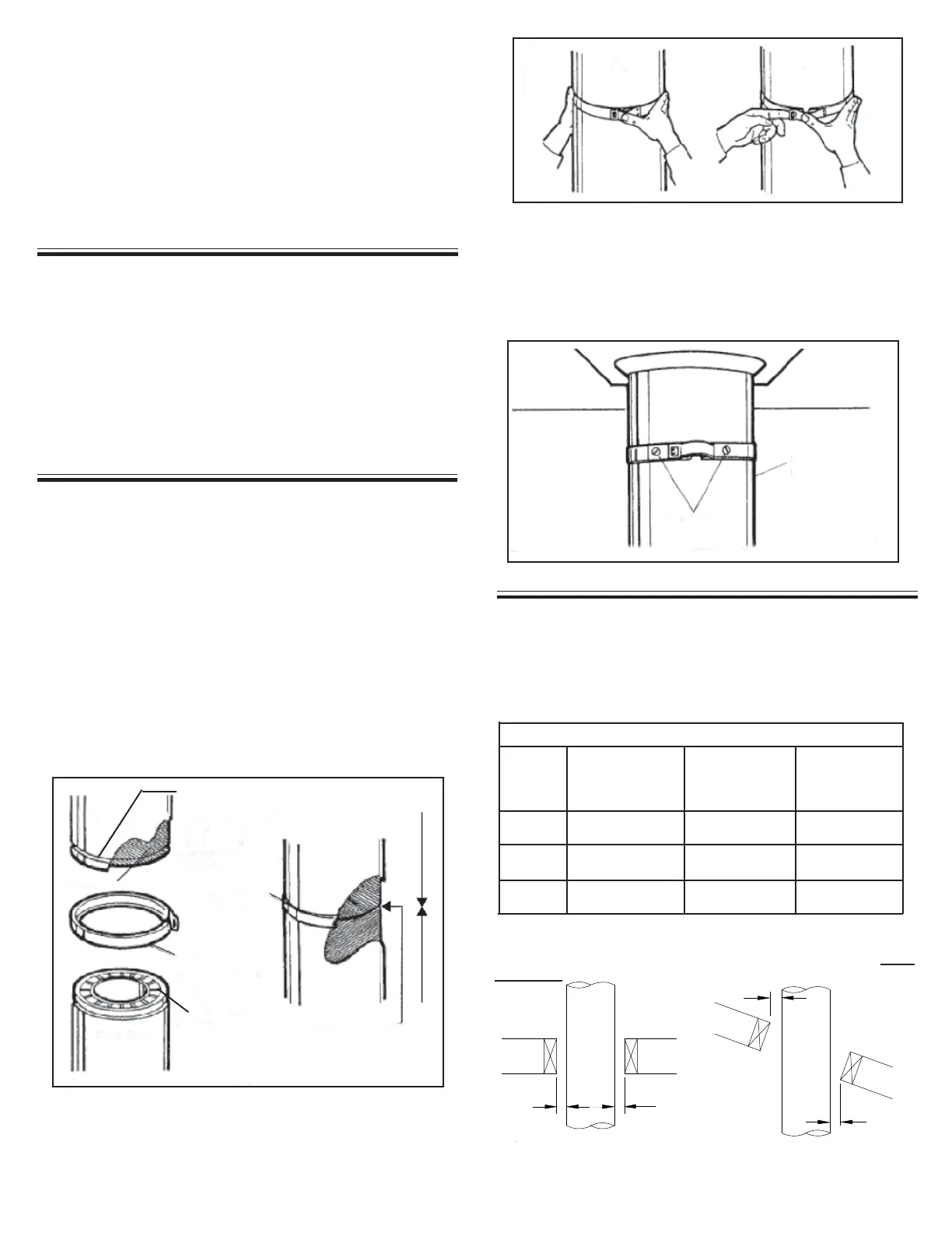
INSULATION COMPRESSION OF THE CF SENTINEL
Before assembling chimney lengths to one another, the insulation
on the female end (held in place with a plastic retainer) should be
below the outer bead so that it can compress during assembly.
The upper side (male end), should be full of insulation (held in
place with a white paper retainer and a web coupler) to the top of
the length. Once you have assembled the lengths together, a
locking band must be installed. With the insulation being
compressed, this will provide insulation to insulation contact (see
Figure 2).
NOTE: When the insulation retainers melt or volatilize during high
temperature operation, the compressed insulation will fill in.
FIGURE 2
Insulation
Locking Band
Locking Band
Seated All
Around
Insulation to Insulation
Contact
Insulation Compressed
Outer Bead
Suspended Length
Stainless Steel
Sheet Metal
Screws
FIGURE 4
Plan your installation carefully. If possible, position the stove so
that the flue outlet is centered between joists or rafters. Drop a
plumb line to the center of the flue outlet and mark this center
point on the ceiling. Lay out and frame in all openings ensuring
the specified 2” clearance to combustibles is maintained. Refer
to Table 1 or applicable Tables for framing dimensions and mark
the appropriate cutting lines around the center point.
FRAMING DETAILS:
2. To remove the lockband, the clasp is pushed in and then
unhooked (see Figure 3B). Lift the clasp with a screwdriver if
necessary.
3. When a chimney section is suspended e.g: below a Cathedral
Ceiling Support, the band(s) and the joints must be fastened
using two (2) #6 x 1/2" stainless steel sheet metal screws (see
Figure 4).
FIGURE 3
INSTALLING THE LOCKING BAND:
NOTE: The chimney pipe and fittings must be assembled only
with the locking bands as furnished.
1. The clasp lockbands are simply seated in the beads of the
joints and clipped together (see Figure 2 & 3A).
Typical Roof
Joist Framing
FIGURE 5
Typical Joist
Framing
2" Min.
2" Min.
2" Min.
2" Min.
FIGURE 6
TABLE 1
*Note: The clearance to combustibles obtained with a correctly
installed Ceiling Support Assembly in the framed opening
specified above has been tested. The 2 inch clearance
does
not apply at this location.
*Ceiling
Support
Wall
(Support)
Thimble
Framing Dimensions
All Other
Framing
Chimney
Flue
Diameter