11
NOTE: If complete framing of the vertical wall opening is not
practical, the Wall Plate Spacer and the Exterior Wall Plate must
be substituted with an Insulated Wall Thimble (see Figure 21). It
is designed for use in accommodating unframed openings while
maintaining the chimney's required 50mm (2") air space clearance
to combustibles.
- Install the Wall Thimble before installing the Wall Support
assembly.
- Ensure that the proper framing dimensions is respected below
the opening to accommodate the Wall Support (see F "Framing
for Bracing" in Table 3).
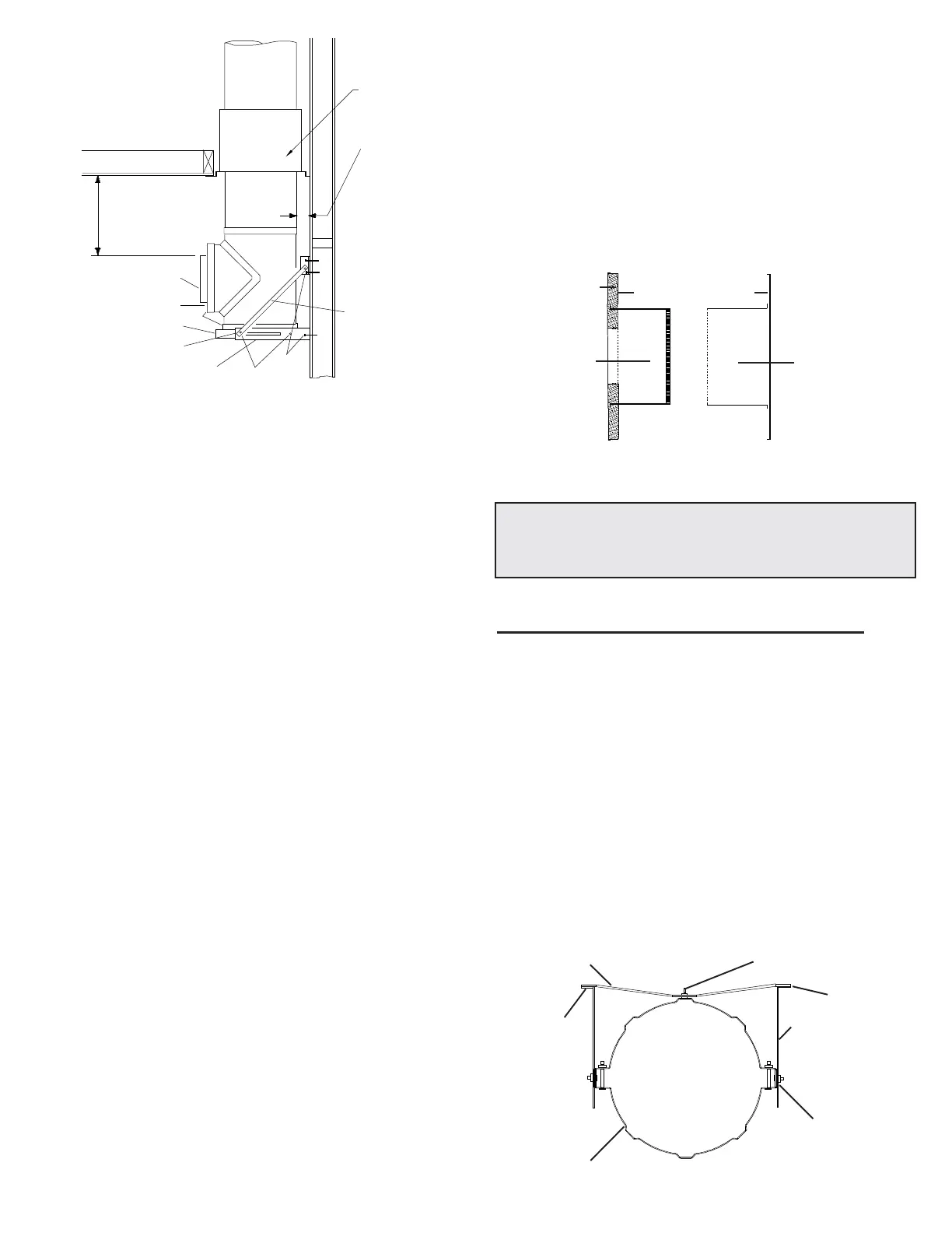
Interior Wall Support Installation
FIGURE 20B
Insulated Wall Thimble
FIGURE 21
Tee Plug retained by twist lugs
Wall Bracket
Base Plate
Locking Band
Smoke Pipe Adapter
Base Cap
Bolt
Lag
Screws
Angle Brace
Refer to the Installation
Codes for clearance to
single wall pipe.
Normally 18" (450mm)
minimum clearance is
required for solid fuel
fired appliance.
2" (50mm)
Minimum
Clearance
Interior portion of
Insulated Wall
Thimble
Exterior portion of
Insulated Wall
Thimble
Telescoping adjustment
from 6" to 11"
Insulation Blanket
NOTE: To reduce cold air infiltration into the dwelling
you can install the optional Universal Shielding Insula-
tion (SUSI) into the Insulated Wall Thimble. See sepa-
rate installation instructions packaged with the SUSI.
Wall Band
FIGURE 22
1-3/4" Carriage Bolt
Strap Under
Wall Bracket
Perforated Straps
Lag Screws
Support Band
Wall Bracket
Pivot Screw In Slot
WALL BAND INSTALLATION (WB)
1. The required 2" (50mm) minimum clearance is established by
the 1-3/4" center (carriage) bolt. Place the 1-3/4" carriage bolt
through the center offset of the band half nearest the wall. Place
single hole ends of the perforated straps over this bolt. Install nut
tight against strap so that straps are horizontal (as per Figure 22).
2. Clamp the two halves of the support band around the chimney
pipe using the long bolts through the band end tabs. First install
the pivot screws.
3. Place the wall brackets (long slotted parts) over the pivot
screws projecting out from the end tabs and hand tighten.
4. Line up the perforated straps and wall brackets, then mark
position on wall for lag screws or anchors to go through both the
straps and brackets.
9. After checking fit, secure Tee to integral basecap of base plate
with a locking band. Install the Tee Plug and turn the two (2) twist
lugs.
10. Use a non-hardening high-temperature sealant (500
o
F) to
seal around the exterior portion of the horizontal chimney length
where it enters one of the following: Exterior Wall Plate, Insulated
Wall Thimble or a concrete wall.
11. NOTE: Only CF Sentinel chimney must extend through-the-
wall. Use the Wall Plate Spacer (or the interior portion of the
Insulated Wall Thimble) on the interior wall to center and support
the horizontal extension. Remember that the chimney pipe
length selected must extend at least 3" (76mm) beyond the wall
and must be centered in the wall opening. The maximum length
of pipe out from the wall is 39" (990mm).
12. Chimney lengths above the Tee are simply stacked and
secured in place with the supplied Locking Bands.
13. To ensure chimney stability above the wall support, Wall
Bands must be used at every 8 to 12 feet (2.4 to 3.6m) intervals
above the support.
8. If the Tee and the Chimney will be fully enclosed in a chase or
shaft or the wall is non-combustible, the exterior wall plate need
not be used.
7. Place this whole assembly (Insulated Tee, Chimney Length
and Exterior Wall Plate) into the wall opening and onto the base
to check centering and clearances. Make sure there are no
interferences. If the Tee is outdoors, keep in mind that the louver
openings in the Exterior Wall Plate must be down to keep the rain
out.
Firestop Joist
Shield Installed
at Ceiling
Level
- If wall thickness is less than 6 inches, trim round inner shield
accordingly.
- Install thimble before installing the Wall Support assembly.
- Insert the 2 halves from opposite sides of the wall. The painted/
insulated section is to be installed from the interior side. Secure
using the supplied black screws.
- The unpainted/exterior half has the larger diameter shield and
simply slides over the interior half. Fasten to wall with suitable
fasteners.
- Seal the perimeter of the exterior plate using an appropriate
exterior sealant.


 To Next Page