13
Elevator Bolts
Support Plate
(Ref. Step 3)
Securing holes to
Pipe
Elevator Bolts for
Support Plate
(Ref. Step 3)
Elevator bolt Through
Appropriate Hole
(Ref. Step 1)
Ta b
Figure 24
1/4” Nut
Lock Washer
Large
Washer
Ta b
Universal Band
Figure 25a
Elevator Bolt with
Large Washer,
lock Washer and
Nut
Support Plate
1/4” x 2” SS Bolt
Figure 25b
2” Clearance
Cage Nuts
Cage Nut
2” Clearance
Figure 26
7. Center the assembly in the opening. Adjust Plates to the
pitch of the roof and tighten the nuts (see Figures 25b & 26).
8. Install six wood screws (#10 x 2-1/2”) per plate with the
innermost going into rafters or headers.
9. Add additional lengths of pipe as necessary, above and/or
below.
10. Complete installation of the Flashing, Storm Collar and
Round Top as per main installation instructions.
Securing
holes to Pipe
Elevator Bolt with
Large Washer,
lock Washer and
Nut
To Install:
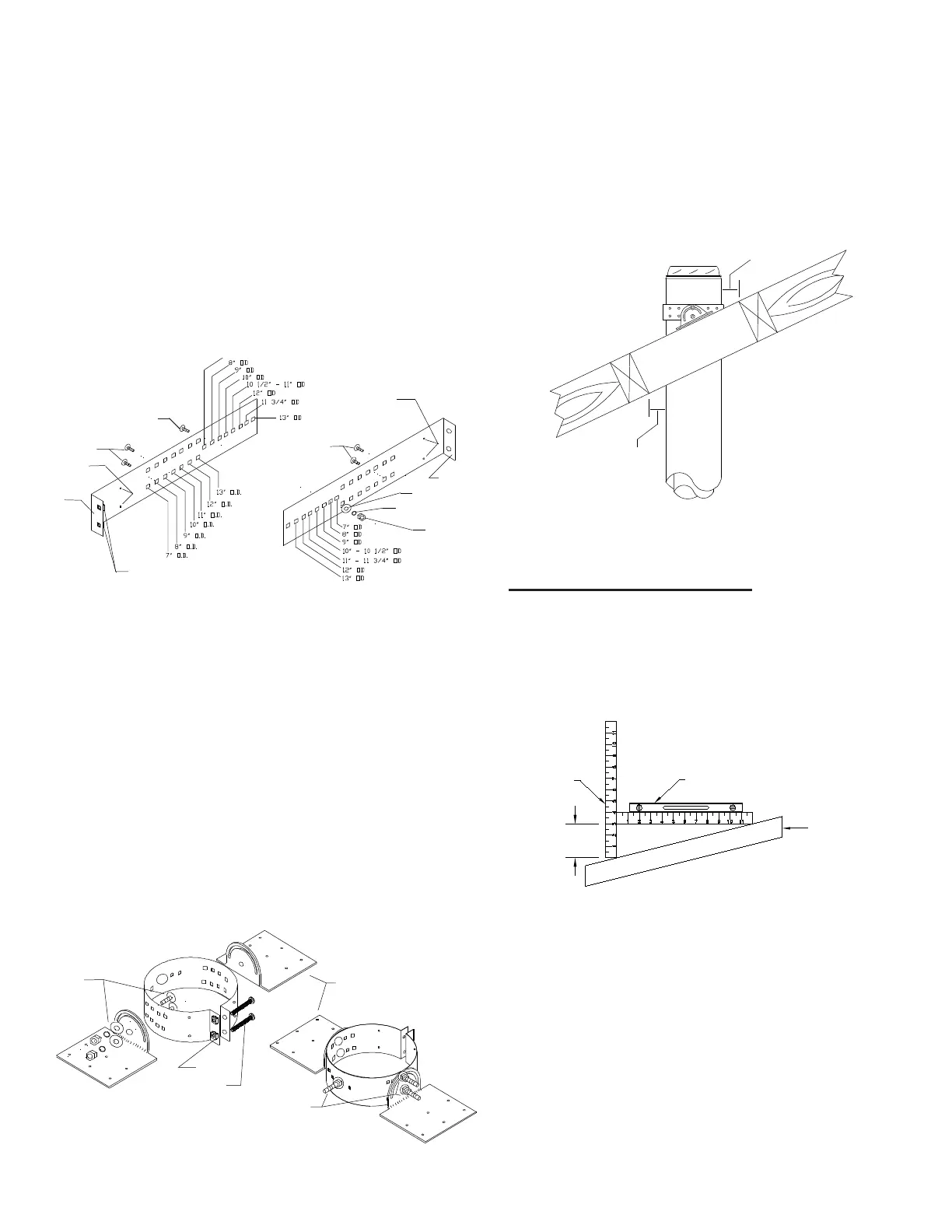
1. Place the two halves of the URSA Band as shown in Fig.24.
Insert elevator bolts through the single row of holes identified
with the outside diameter of the chimney being installed, (Ex.
- for an 8” OD chimney, place the elevator bolt through the holes
identified for 8” OD). The flat head of the bolt should be oriented
opposite the direction the formed tabs are pointed. Secure the
center bolt with washers and nut (see Figure 24).
2. Form the Band into a circle and loosely connect both tabs
using the supplied 2” bolts into the 2 cage nuts (see Figure
25a).
3. Attach the Support Plates to the band with flat head bolts (2
sets per plate) washers and nuts. The bolts should pass
through the holes in the band corresponding to the pipe
outside diameter and secured loosely (see Figure 24 & 25A).
NOTE: 2 sets per Support Plates.
4. Place assembly around the length of pipe and loosely tighten
the tabs with the screw and nut referenced in Step 2. Move
the assembly to the desired height location on the pipe.
Firmly tighten bolt and nut to secure the band around the
pipe.
5. Secure URSA to the length of pipe by using four (4) 1/8” x 1/
2” stainless steel self-tapping screws (provided) through the 2
securing holes found closest to the tabs on the band (see
Figure 24).
6. The URSA is mounted directly on the roof sheathing with its
Support Plate resting over rafters or a framed opening to form
a solid base. Frame a rectangular roof opening to ensure a
good distribution of weight load. Be sure to allow for a
minimum of 2” airspace clearance to combustibles as shown
in Figure 26. Reference the main chimney installation
instructions for frame specifications and other details.
Level
Roof
Pitch is 3/12
3"
12" Ruler
FIGURE 27
Roof Pitch Calculation
Ensure that you have the proper roof flashing by checking your roof
pitch using a level and two rulers (see Fig. 22) or by using a roof pitch
card.
The FRA-A flashing is for roof pitches from 0/12 to 6/12.
The FRA-P flashing is for roof pitches from 7/12 to 12/12.
ROOF FLASHING: (FRA)
Frame a RECTANGULAR opening to suit the pitch of the roof and
ensure that a 2" (50mm) minimum clearance is maintained to
combustibles.
In new construction, slide a Roof Flashing Assembly suitable to
your roof pitch over the chimney.
On an existing roof, center and install the flashing before extending
the chimney above the roof. Do not nail the flashing to the roof yet.
NOTE: Prepare roof area by removing shingle nails and cutting
roofing material allowing 2" clearance to the chimney. Slide the top
edge (nearestthe roof peak) of the flashing suitable for the roof pitch
under the roofing shingles. At least half of the flashing sides
should be UNDER the shingles and the lower end OVER the
shingles to provide a watershed. Trimming off the shingles may
be neccessary around the
 Loading...