15
Figure 31
Topview assembly of Support Band -
Elevator Bolt, Washers and Nut
Flanged Nut
Flat Washer
Support Band
Halves
Elevator
Bolt
D. From the double rows of holes (upper or lower row) select the
hole in each halves that corresponds to the OD of the
chimney. Insert 2 elevator bolts (1 per side) through both
holes.
Lock Washer
Cage Nuts
E. Position the Support Band approximately two thirds of the
way up the chimney height (see Figure 35). The preferred
location is next to a joint, immediately above or below a
Locking Band. Secure Support Band by tightening the 2”
bolts.
NOTE: Only one chimney joint should be above a Roof Brace
Kit, the addition of a secondary one may be required.
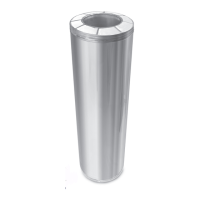
F. Assemble the telescoping legs by sliding the supplied hose
clamp over larger diameter leg and then inserting smaller
diameter leg into larger diameter leg. Temporarily hold legs
together by tightening the hose clamp over the cut section of
larger diameter leg (see Figure 32). Repeat for the other
telescoping leg assembly.
Smaller Diameter
Telescoping Leg
Cut Section of Larger
Telescoping Leg
Larger Diameter
Telescoping Leg
Pilot Hole for
Securing Screw
Hose Clamp
Figure 32
Assembly of Telescoping
Legs with Hose Clamp
Elevator Bolt
Angled end of
Telescoping Leg
Flat Washer
Lock Washer
Flanged Nut
Elevator Bolt
Angled end of
Telescoping Leg
Flat Washer
Lock Washer
Flanged Nut
Figure 33
Assembly of Telescoping
Legs to Support Band
Flange Nut
Smaller Diameter
Telexcoping Leg
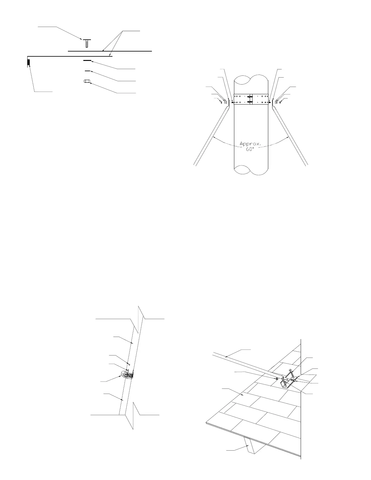
Roof Shingles
Rafter or framing
structure
1” Bolt
Angle Bracket
2” Lag Screws
Figure 34
Securing
Angle Bracket
G. Attach each of the telescoping legs (angled end) to the 2
elevator bolts on the Support Band with supplied washers
and nut (see Figure 33).
H. Attach one end of each telescoping leg assembly to each of
the Angle Brackets using one (1) 1/4-20 X 1” bolt and nut (see
Figure 34).
2” Lag Screws
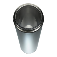
K. The two telescoping legs should form an angle of about 60°
to give support to the chimney in all directions. The angle of
the telescoping legs should not be more than 45° from
horizontal when fastened to the roof (see Figures 33 & 34).
I. Determine the location of the two Angle Brackets on the roof
structure. Ensure the fasteners are into rafters or framing and
not just roof sheathing. Secure the Angle Brackets to the roof
structure using two (2) 1/4 X 2” lag screws per brackets (see
Figure 28). Seal the roof with a suitable non-hardening
waterproof caulking.
J. Make sure the chimney is level and plumb. Check all required
dimensions and angles, adjust if necessary. For added
security, you may lock in place the telescoping legs by using
1/8” x 1/2” stainless steel self tapping screw (supplied)
through the pilot holes found near the hose clamps (Figure 32).
Secure the Support Band to length of pipe by using four (4) 1/
8” x 1/2” stainless steel self-tapping screws (supplied) through
the 2 securing holes found closest to the tabs on the band (See
Figure 29). Cover screw heads with a suitable caulking.
 Loading...