IAtor
to
produce
• lingle
IF
froquency. A
lecond
type
of
receiver
USN
dllQl CO"""",,;.,,,.
In
thil
receiver, the
incominll
RF
aigna.!
iJ;
converttd
to
one
IF
frequency,
and
then
mixed
with
II. seoDnd loeal oecillAtor
to
pr0-
duce
II.
tIeCOnd
(lower)
IF
frequency.
While
455
KHx
ia.
common
IF
fftquency
found
in
both
lingle·
and
dual..convel1lion
receiwrl,
there
ue
many
other
IF
frequencietl
U8ed.
In
geneTa.i,
the
IF
frequency can be anyiliing [rom
4.55
KHz
to
12
MHz
od
jWlt
about
IIJIY frequency
in
between.
For
thill reason, the CB42 provides
II.
fully .c:tjultable
If
generator providing
375
KHz-12
MH:z.
...-
..
,.
Cottom""
"
AmIJIifief
'"'_ Clv.t.l1s
.....,..
I
AGe
VolU91
.
_~
r-,I,-;';'''i.~r-'''''",
"'
Amplilio,
t.:
'or,'
::J
r.=~,_,
/ I
Osdlolor
Mouu,e
F,elluencv
Or
AF
VOltllg.e
•
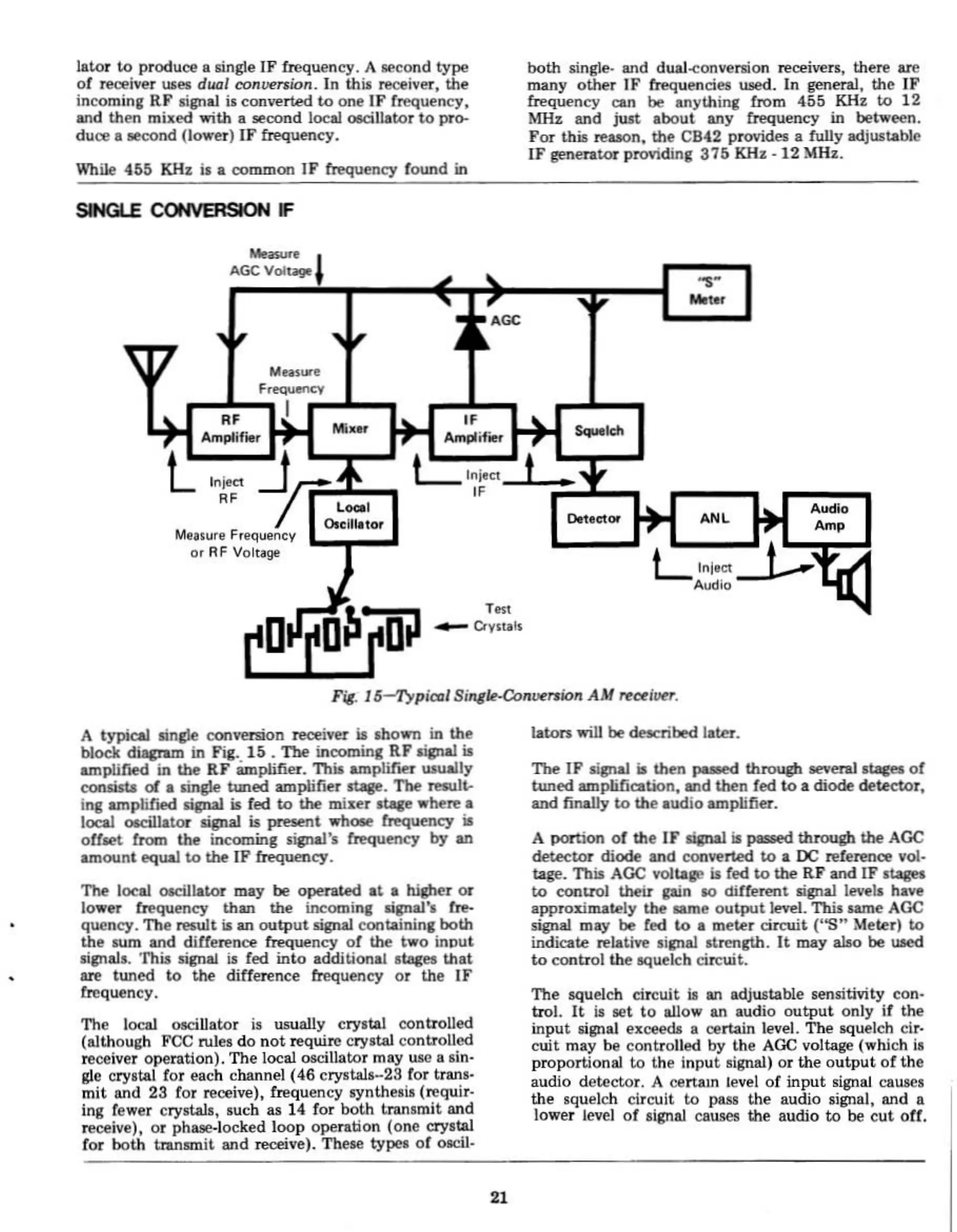
A
typical
llinde
conversion receiver
ia
lhoWll
in
the
block
diacr-m
in Fig.
15.
The
incoming
RF
ligna.! ir;
amplified in the
RF
amplifier.
Thia
amplirlU
UJually
COlUiau:
01
II.
lingle
tuned
amplirlU
atII.ge.
The
J'@Al1t-
ing II.lllplirted
aignaI
ir; fed
to
the
miser
..
where
II.
local
OKill&t.oF
ligna!
ia
JIlftl!flt
whoR
frequency ir;
offaet
from
the
incoming signaI'a frequency
by
II.Il
amount
equal
to
!he
IF
~uency.
Tbe
local oociIlator may be
operated
a~
II.
higher
or
lower frequency
than
the
incoming Iignal'l fre-
quency.
The
reawt
is an
outputlign.al
containing
both
the
sum
and
diUerence frequency
of
the
two
inout
aiJllall. 'I'hia lignal
i.
fed
into
additional atq:es
that
lIll!
tUlled
to
the
difference frequency
or
the
IF
frequency.
The
local oacillator
il
usually
cryltal
controlled
(llithough
FCC
Nlea
do
not
require Cryltal
controlled
receiver
operation).
The
local oacillator may ulll a
lin·
g1e
cryltal for
each
channel
(46
cryltala-23
for tranl-
mit
and
23
for reoeive), frequency
Iyntheail
(requir.
ing fewer
crystab,
luch
as 14 for
both
lranlmit
tlnd
receive),
or
phue-locked
loop
operation
(one
crystal
for
both
tranr;mit
and
receive). These
typl'll
of
olCiJ-
Iaton"";U
be deacribed later.
n.e
IF
sipa.I
iI
then
puled
through
ae\'enl1tar5
of
tuned
amplification, Uld
then
fed
to
II.
diode
detector,
and finally
to
Ole
audio
amplifier.
A
portion
of
tne
IF
&ijnaI ir; pasHd
through
the
Ace
detector
diode
and
con~rted
to
II.
DC
",ference
vol.-
tage.
This
AGe
voltll.je
ia
fed
to
the
RF
and
IF st.agel
to
eontrol
their
gain
10
differmt
lignal levell have
II.pproIimately
the
ume
output)evft.
Thill aame AGC
signal may be fed
to
a
meter
circuit
('OS" Meter)
to
indicate relative liJllal
Itrength.
It
lDII.y
abo
be
used
to
eontrol
the
&Quelch
circuit.
The
lQuelch circuit
it
an
adjustll.b1.e
aenlitivity
con·
trol.
It
II
aet
to
allow
an
audio
output
only
if
the
input
lignal exoeeda a certain level.
Thfo
llQueleh cir.
cuit
may
be
controlled
by
the
AGe
voltage (which
II
proportional
to
the
inpu~
signal)
or
the
output
of
the
audio
detector.
A oertam level
of
input
lignal
caUlof)S
the
$queleh circuit
to
pus
the
audio lignal,
and
a
lower
level
of
ligna! Cll.UK'll the
audio
to
be
cut
oU.
21