8.
Adj
..
t
the
receiver volume control
to
maximutIl.
9.
Set
Ule
DlGlT
AL
READOUT SELECTOR
t<:l
EXT
FREQ
{l
Meg
load) posit.ion.
10. AdjUit the receiver clarifier for • reading
on
the
DIGITAL
REAOOln
of
1.00
KH1..
U.
Set
the
DIGITAL
READOur
SELECTOR
to
the
AUDIO WATTS poI$iton.
12.
Read
the
audio
output
power
OIl
Ule
DIGITAL
7.
Set
the
MICROVOLTS OUTPUT
controls
to
REAOOlJr.Aproprrlyope:ratingn'Cl.'iveuhoulfl.-
provide SOuV
ofliCnal
(ll
lOud
~c'
f;"'vide
2-4
WatU.
This
test
mlY
be
performed
on
nell
or
the
chan~b
by
rotating
the
channelll!lector
swiI-Ch
of
the
receiver
at
Ule
same
time
as
the
CB
RF
TUNER.
It
should
not
be
necessary
to
reset the clarifier control for each
channel.
Changes in
Ule
output
rrequeney
of
more
tluln t KHz indicatel an
off·f~uency
cryllal
in
the
receiver
ioc:aI
o.a.JlaUW. This
test
may
also
be
made
on
the USB f\1lletion
by
repeatinl
Slol'p5
9-12.
If
Lhe
clarUlIl'r mllSt
be
shifted
m<.>re
than
15"
for a 1 KHz
n'lldout,
the
alignmmt
of
the l'eQI!iver IboukI
be
considered.
SSB
RECEIVER SENSITIVITY
ca
II'
T~II
T
.
i..~
~""""
:o'ot)'
,.,nn::rnn
....
u
....
'
•.
<.1
U
..
'
~o--I
• •
a
......
<;:o
....
..
,~
......
m
...
~,"~
,
'"
..
'
0
'''11111''''
......
Af'."
lllllllRArOR
AUOIO OIGITAl
III.AOOUT
Mucr_
,:;:@).
0
"0
,·Cr.".""
..
,...
.
I
II
I
Cl
MICROVOlT
OUTIOUT
.~~'~':f"",
"
,.
• 1 1 ,
BIOZAKUI
Bua
..
:~::.
o.
'"
:~~::
0
;;:-:1',~"
,
~
a.a~":r'NG
OUT~r
SlGNAU
"'OOI~
OlGna~
RlAOOUT
.-or
SlG.A~.
..
G
•••
...
.....
..
•
I'D
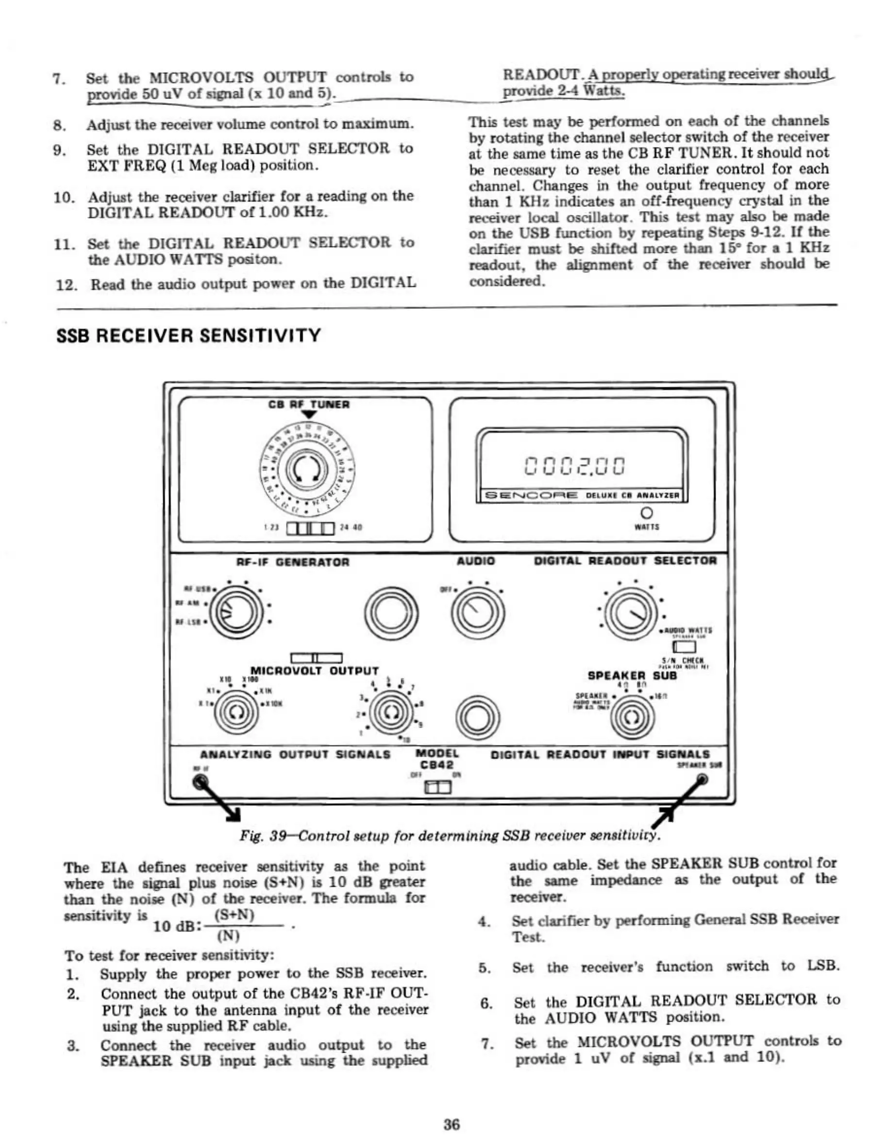
Fil.
39-Control
fefup
for determining SSB receiver
3en,iti~iry.
The EIA definell receiver aensitivity u the point
""ben!
Ule
.~
phil
n01Je (S+N)
it
10
dB treaw"
than
the noise
(1'1)
of
the receiver.
The
formula
for
WNitivity
it
(5+1'1)
10
dB;
(1'1)
To
ten
fOl"
~oeiYer
M!lUitivity:
1.
Supply
the
proper
po
...
er
t<:l
the SSB recei""r,
2,
Connect
the
oUlput
of
the
CB42's
RF·IF
OUT-
PUT
jack
to
the
antenna
input
of
the
receiver
ulinl
the
supplied
RF
cable.
3.
Conned
the
receiver
audio
output
t.o
the
SPEAKER SUB
input
jack usinC the
.upplied
audio
cable.
Set
the
SPEAKER SUB
control
for
the same impedance u the OIItput
of
the
reoeiver.
4.
Set clarif'lIl'r by
pedonninl
Genem
SSB Receiver
Telt.
5.
Set
the
receiver'. function JWitch
t<:l
LSB.
6.
Set
the
DIGITAL READOUT SELECTOR
to
the
AUDIO WATTS poIition.
7.
Set
the
MICROVOLTS OUTPUT controls
to
provide 1 uV
of
lignal (,..1 and
10).