To
perform the
~ceiver
sensitivity
wit:
1.
Supply
the
proper
power
to
the
CB
re<:eiver.
2. Connect the
output
of
the
RF
·IF OUTPUT jack
to
the
receiver's
antenna
jack using the supplied
RF
cable.
3. Connect
the
audio
output
of
the
~ceiver
to
the
SPEAKER SUB input
of
the
CB42 using
the
.upplied audio cable. Set
the
SPEAKER SUB
switch
to
the proper impedance
to
match the
output
of
the receiver.
4.
Set
the
CB
CHANNEL TUNER
to
the
same
channel as the
eB
receiver.
5.
Set
the internal
audio
generator
to
1000
Hz
and
the AUDIO MODULATION
switch
to
30%.
6. Set the DIGITAL READOUT
SELECfQR
to
the AUDIO WATTS position.
7.
Set
the receiver'. volume control
to
maximum
gain, and
squelch
to
minimum.
ADJACENT
CHANNEL
REJECTION
8.
Set
the
MICROVOLTS OUTPUT controls for
1
uV
output
·(x.1
and
10).
9. Read the audio
output
power on
the
DIGITAL
READOUT.
10. Depress the SIN CHECK pushbutton
and
read
the DIGITAL READOUT with
the
button
de.
prea&ed.
11.
If
the reading ill higher with the
button
de·
prelSCd, the noise figure is greater than
the
signal
plus noise, so
the
signal must
be
inCretllled
by
increasing
the
output
of
the
MICROVOLTS
OUTPUT
controls.
If
the reading ill lower
with
the
button
de-
pressed,
the
signal figure is greater than
the
noise, so
the
silP'llll
must
be
reduced by decreas-
ing
the
output
of
the MICROVOLTS OUTPUT
controla.
The
point
where the same readout
is
obtained
with
the
button
in
or
out
is the
10
dB (S+N){N point.
The
te<;>!iver
sensitivity ill simply read from the
two
MICROVOLTS OUTPUT controlll.
ell
IIF
TUNEA
~
''''".
~
~,,~n~,:.
:/0«:
n,",-,:-nn
., ".
LIUL'L.UU
.'
!J >•
..
'
'-
"
•
<'
s_
.....
co
__
Ct,
••
, ,
....
,
••
,.
• • •
.
..
•
'"
.
•
0
'''111111''''
.tm
AF_IF
GENEAATOA
AUDIO
DIGITAL
AEAGOUT
SELECTOR
·'·:0:
.
~
..
,
}o:·
....
"
..
---
0
0
...
I
n
I
MICAOIIOLT
OUTPUT
SPEAKEA
SUB
·::i::·
,
.::,~::
•
~
~o
0
,
......
~'"
~=
..
u;:!~
••
ANALYZING
DUTPUT
SIGNALS
MODEL
DIGITAL
AEADDUT
INPUT
SIGNALS
••
CII.2
.....
"-
••
•
m
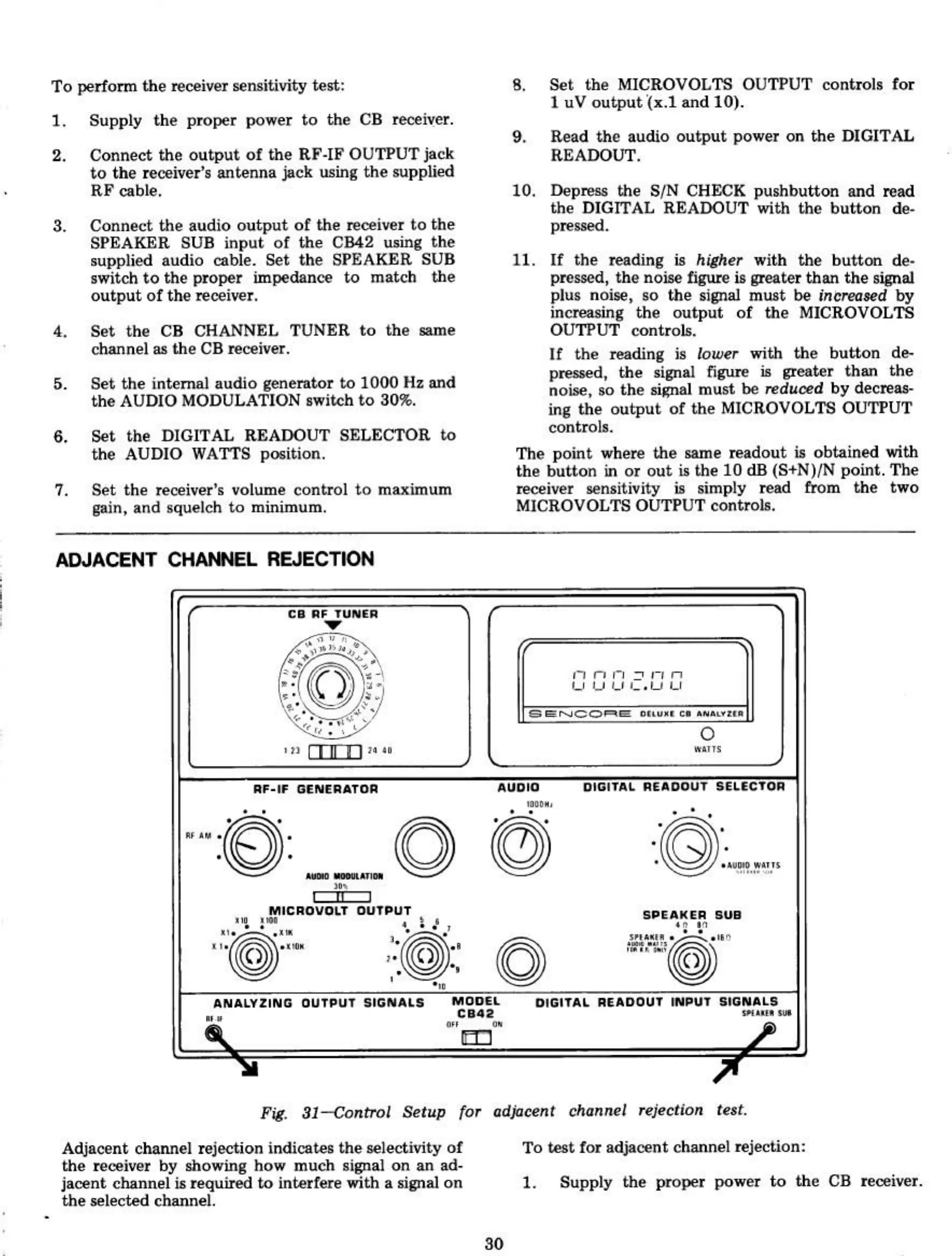
Fig.
31-ccmtrol
Setup
for
lIdjllcent chllnnel
re~Clion
te,t.
Adjacent channel rejection
indica~s
the selectivity
of
the receiver
hy
showing how much signal
on
an ad-
jacent channel ill required
to
interfere with a signal
on
the
selected channel.
30
To test for adjacent channel rejection:
1.
Supply
the
proper power
to
the
CB
receiver.