4,
Rnd
the
pereentage
of
difference from
the
DIGITAL DISPLAY.
NOTE: ,
......
11'1'
SSB
tn
.....
men.
1ll.
HCI
..
if;""~
_.01
.........
the outPUt frtqUtfM:Y
of
Ih.
IrI
..
-.lin
..
liIithtly.
'MIen
chtckilOg
1ll.
fint
dlmlltl',
trlmmltt8r 1lTOI',
let
Ihls
COIIlfoi for • mi
...............
illll
01
..
ror
01\ ItM DIGITAL
REAOOUT.
The
tWlini:
ranpl
of
the
dorirll:r control should
not
Cl.UIe
the
transmitted
frequency
to
iO
beyond
the
.
OOfl~
tolerance
aUo"Ved
by
the
FCC.
To
test
thio function:
SSB
TRANSMITTER ClARIFtER CONTROL TEST
1.
Set
up
the
PERCENT
OFF
CHANNEL
TEST
described
in
the
previoua
pangnph.
2.
Rotate
the
clarifier Ihroug/\
ia
tunina: n!npl.
The
percent
off
clwmnel
IndicaLion
mould
not
read
over
.OO5~
at
any
lIettinr
of
the clarifier
control.
SCOPE ADAPTER APPLICATIONS
;I. 100.
The
IICllPC
adapt.el' oulpUt allows
the
modulation en·
velope
of
the
tn_itt«
OUlp.lt
to
bII!
moa~
U$iq
any
~1>e
...
1purpooe
oec:ill0a00pe
..
ith
at
1_
a I MHz
band
..
idth.
The
inatruetiola
for hookup for
leneral
..
a,·eform analysio ano included
in
the
~I
Opwa.
t
.....
oeetion.n.e
roll"...."
r
...
,.
tt--
typieal modula.
tion
envelol-
AM Modulation
Fia:.
46 Ibows
an
un-
modulated
carrier.
By
applyinC
modulation,
tbe
modulation en"elope can
bII!
Iftn.
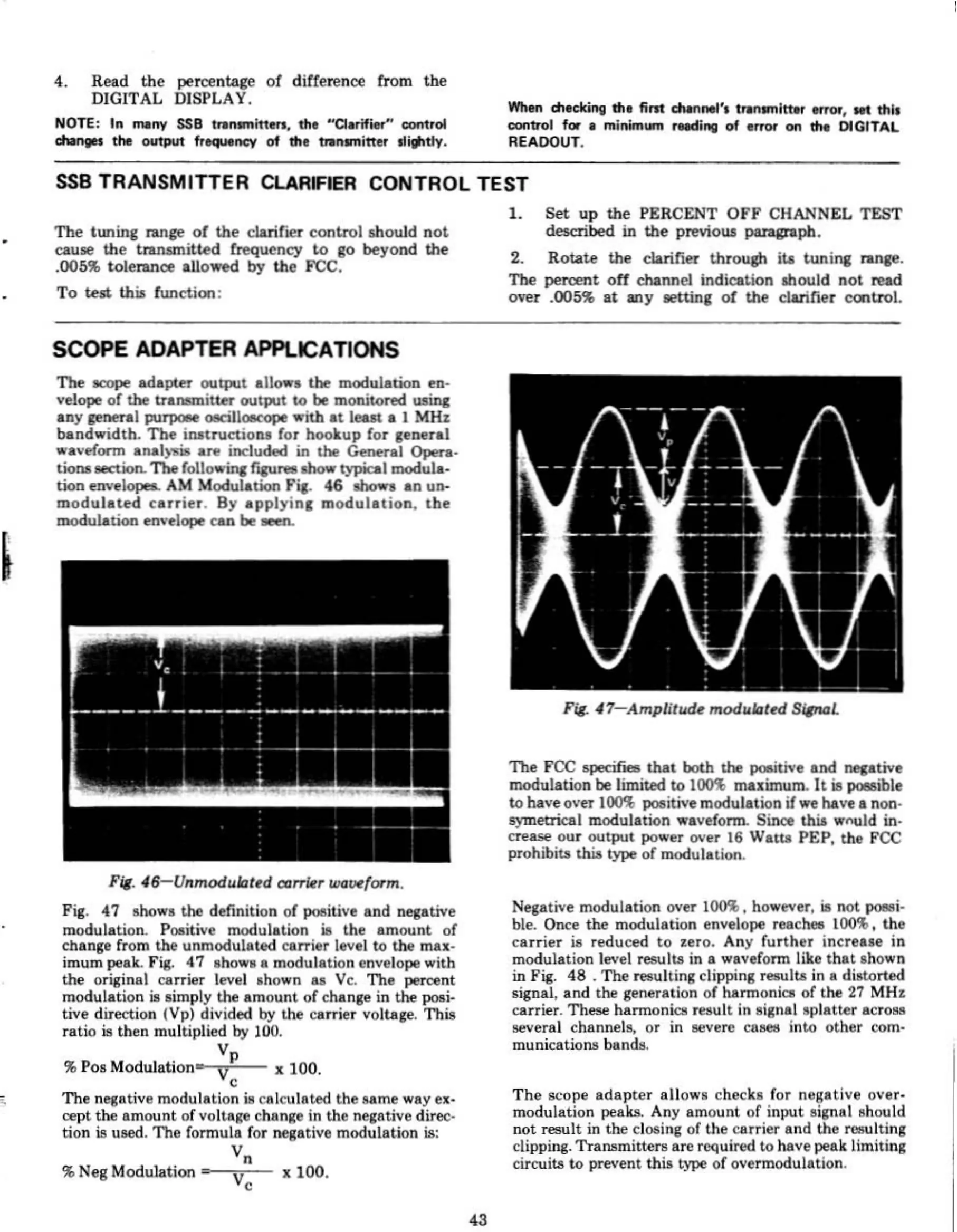
Fie. 47
mo
... the definition of poIlitive and negative
modulation.
POOIitive
modulation ill the amount of
change from the unmodulilted
curier
level to
the
mn-
imum ""air..
Fia;.
47 shows a modulation envelope with
the original carrier level lhown
as
Vc.
The
peralnt
modulation;'
simply
the
amount of change in
the
poIli·
tive direction /Vp) divided
by
the
c.rrier
voltage. This
ratio is then multiplied
by
100.
V
p
~
Pos Modulation'-'V,.,'----
;I.
100.
The
n"ll.t;ve
modul.tion
ill celculated the
••
me
way ex·
rept
the
amount
of voltage change
in
the
neg~tive
direc·
lion
is
u&ed.
The
formula for nq:ative modulation
is:
V.
% Neg Modulation
-~ri-
V,
43
F~
47-AmplituQ~
mQdlllattd
S/6ML
The FCC
epecii_
that
both the pooitive and TIeI.tive
modulation
bII!
limited to
100%
maximum.
It
is poIIible
to haveover
100'1.
pOOIitive
modulation if
we
have e non·
5}'IIIetrical modulation
....
veronn. Since thi5 wnuld in·
creal;(!
our output
PO"'"
over
16
Watts PEP,
!hi
FCC
prohibits
tm.
type
of
modulation.
Negative modulation over 100%, ho
...
ever,
is
not
JlOMi·
bie. Once
the
modulation envelope reachea
1000000,
the
cu.ier
is
~duced
to
u'o.
Any
further
increue
in
modulation
It'Vel
results in • "'lVefoml like
that
.hown
in
Fia;.
48.
The
....
Illting dipping results
in
a di.torted
.ignal, and the gen&ration of Iuormonial
of
the
27
MH~
carrier. These harmonica
"",ult
in
signal eplRtler
aCrOM
leveral channels, or in llevere
Ca1e8
into other
tom·
municatiOTl!l
b~nd!l.
The
leope
adapter
allow.
checks for negative over·
modulation peaks. Any amount of input eignal ehould
not
.....
ult
in
the
dosing
of the carrier and
the
l'eIIulting
dippitlll. TraTlllmittere are required
to have
pe.klimiting
citroi
..
to
pTt'Vent
thi! type
of
overmodulation.