AM
RECEIVER
TESTS
I
I
AootO
OUTPllT
POWER
'"lldll""
IIf·"
GENEAArOIl
I
our"",
,::6::
,
'.
auo,o
,-,nn::Jnn
UUUL.UI..I
o
~.,,'
D'GIfA~
RUlDOUT
IEUCTOII
IPEaKEA
$UI
..
n
;;,::!:o~.,
i
I
ANALYZING
OUTPUT
.'GNALB
MODU
C
....
.' .
rn
DIGITAL
READOUT
'NPUT
"DNUI
...
.......
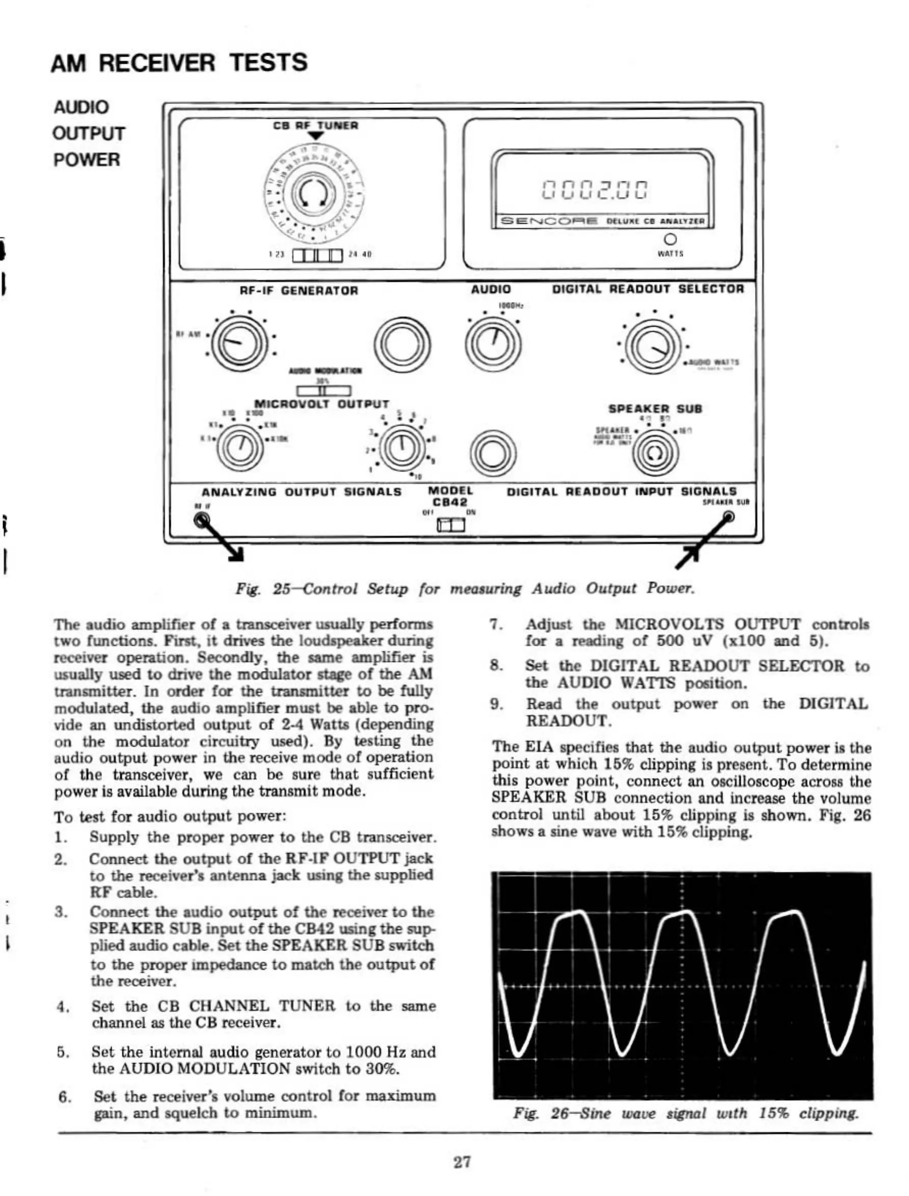
Fig.
25-<:<Mtrol
St:tup tor m<!llwrilll
Audio
Output
PoWf'r.
I
n.e
audio
ampliroeT
of
..
tralUCft\'et
uaually
pert'onM
two
function.s.
Fint,
it
driws
the
loudlpeaker
durinB
~
operation.
Se<'OI'ldly,
the
lIaITIe
amplifier is
UliUaUy
Il!led
to
drive
the
modulator
d.BCe
of
the
AM
uansmiuer.
In
orde!"
for the tranlmitter
to
be
fully
modullted,
the
.udio
amplifier mUll
be
able
Lo
pr0-
vide an
undistorted
output
of
Z-4
W.lU
(dependinl
on
the
modulator
circuitry
uRd).
By
testing
the
udio
output
power in the receive mode
or
operation
of
the transceiver,
we
can
be
lure
that
sufficient
power
il
available during the tmnamit mode.
To
test for
audio
output
power:
L Supply
the
proper power
to
the
CB
lranloCl'iver.
2. Connect
the
output
of
the
RF-IF OUTPUT jack
to
\be
receiver',
anU!nn1
jack
lIIinl
the
supplied
KF
cable.
3.
Conne<:T.
the audio
output
of
the
re<ltiftr
to
the
SPEAKER
SUB
input
of
the
CB42111inl
the
1Up-
plied audio cable.
Set
the
SPEAKER SUB
Poitch
to
the
proper
Impedance
to
match Ihe
output
of
the
reoPiver.
4.
Set
the
CB CHANNEL TUNER
t.o
t.he
owne
channelu
the
CB re<:elver.
~.
Set the internal audio generator
t.o
1000 Hz and
the AUDIO MODULATION
switch
to
30'%.
6.
Set
the
receiver', volume control
for
lDiuimum
pin,
and Mlueleh
to
minimum.
27
7. AdjUlt
the
MICROVOLTS Ol1l'PUT conU'OIa
f(X
a
rMding
of
500
uV
(1:100
IlI1d
5).
8.
Set
the
DIGITAL READOUT SELECTOR to
the
AUDIO WATTS poIition.
9.
~i>d
the
output
power on the DIGITAL
READOUT.
The EIA
IlpecifieJi
that
the audio
output
power u the
point
at
which 15':\ clipping is present.
To
determine
this
power
point,
connect an
*iII0KCope
aerou
the
SPEAKER SUB connection
and
increase
the
volume
control until
about
15% clipping u shown. Fig. 26
shows a sine wave with 15% clippinl.