The
impulse noise limiter test
detennines
the
effec.
tiveness
of
the
Aut<Jmatic Noise Limiter (ANL)
or
Automatic
Noise Blanker (ANB) circuits
in
the
receiver. These circuits llhl designed
00
reduce inter-
ference from
$IIch
sources as automotive ignition sys-
tems and
high power
AC
lines. The test requires
the
use
of
the
optional
NL204
Noise Pulse Simulator.
The
NL204
consists
of
a noise spike generator wllich
feeds a 1 Volt Peak.to.Peak signal
into
a 6 dB
"T"
mixing
pad.
In
operation,
the
output
of
the
spike gen·
erator
is mixed
with
the
signal
output
of
Ule
CB42
and a signal·tn-noise test performed.
To
test
the
operations
of
the
ANL and ANB circuits:
1. Supply
the
proper
power
to
the
CB
re<:eiver.
2.
Connect
the
output
of
the
C842'.
RF.IF
OUT.
PUT jack
of
the
INPUT JACK
of
the
NL204.
3.
Connect the OUTPUT
JACK
of
the
NL204
to
the
antenna
input
jack
of
the
receiver.
4. Set
the
re<:eiver ANL switch on, and squelch
to
minimum.
5.
Set
the
CB
RF
TUNER
to
the
same channel
all
the
receiver.
6. With
the
NL2Q4
turned
off, perform
the
EIA
Sensitivity
Test
as described previously.
NOTE: Sinee
the
output
of
the
CB42
is
dropped
6 dB
by
the
m..ixing
circuit8
of
the
NL204,
the
reeeiwr
should
reo
quire twice
as
much
output
from
the
CB42 for this test a.'I compared
to
the
standard
sensitivity test.
7. Note
the
llCUing
of
the
MICROVOLTS OUTPUT
CQntrols
for
the
10
dB (S+N)/N point.
8. Adjust
the
NL204 to
the
calibrated 1 V
pop
po-
sition,
and
repeat
the
EIA Sensitivity Test. More
output
from
the
CB42 should
be
required
to
reach
the
llCcond
10 dB point.
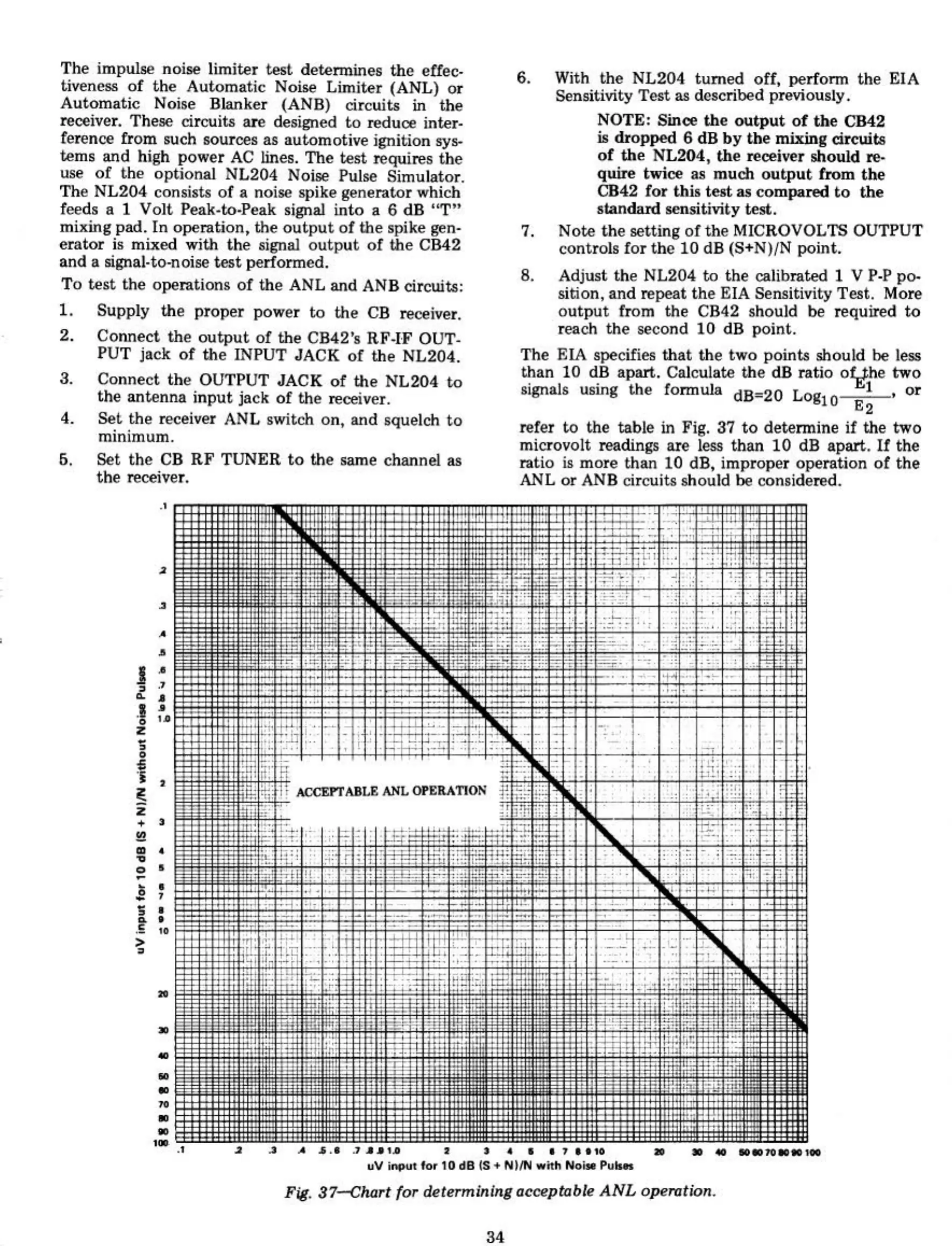
The
F.1A
specifies
that
the
two
points should
be
less
than 10 dB apart. Calculate
the
dB ratio
o~he
two
sillJlals using
the
formula
d8"20
Log
I,
or
10 E2
refer to the table
in
Fig. 37
to
determine if the
two
microvolt readings
are
less
than
10
dB
apart.
If
the
ratio is
more
than 10 dB, improper operation
of
the
ANL
or
ANB circuits should
be
considered.
2
.. ..
•
•••
,.
,...
•
__
"v
' lor 10
~81S.
NflN
..
iI~
No
...
Pu
....
•
,.. -
'r'
-;:'!:
.,
......
~
. .
J.
, •
~.:
c'
''':-''
,.
.,
..
~.
,
'.""-"
_II
..
•
..
•
•
..
•
•
••
•
•
I
~
.J
~.
•
i ,
~
•
·,
•
·'
• •
! :
I :
·
..
•
•
Fig.
37.-<1Ulrt for determining aceeplllble
ANL
operotion.