SENNHEISER ELECTRONIC GMBH & CO. KG
COMPONENT MAINTENANCE MANUAL
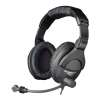
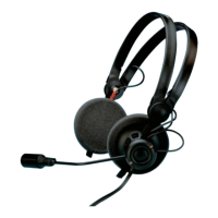
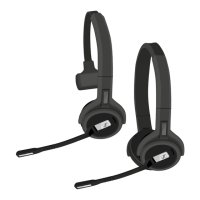
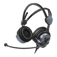
HMEC 26 SERIES
Page 1012
Feb 10/10
23-41-48
4. Fault Isolation
NOTE: DISASSEMBLE THE HEADSET ONLY AS FAR AS NECESSARY. REFER TO DISASSEMBLY.
If you find a malfunction during the tests, you must do more tests to isolate the defective part. This
section gives data that helps to identify the defective part.
The following table gives the identification and the specific function of all the cables of the Headsets
(HMEC 26 series).
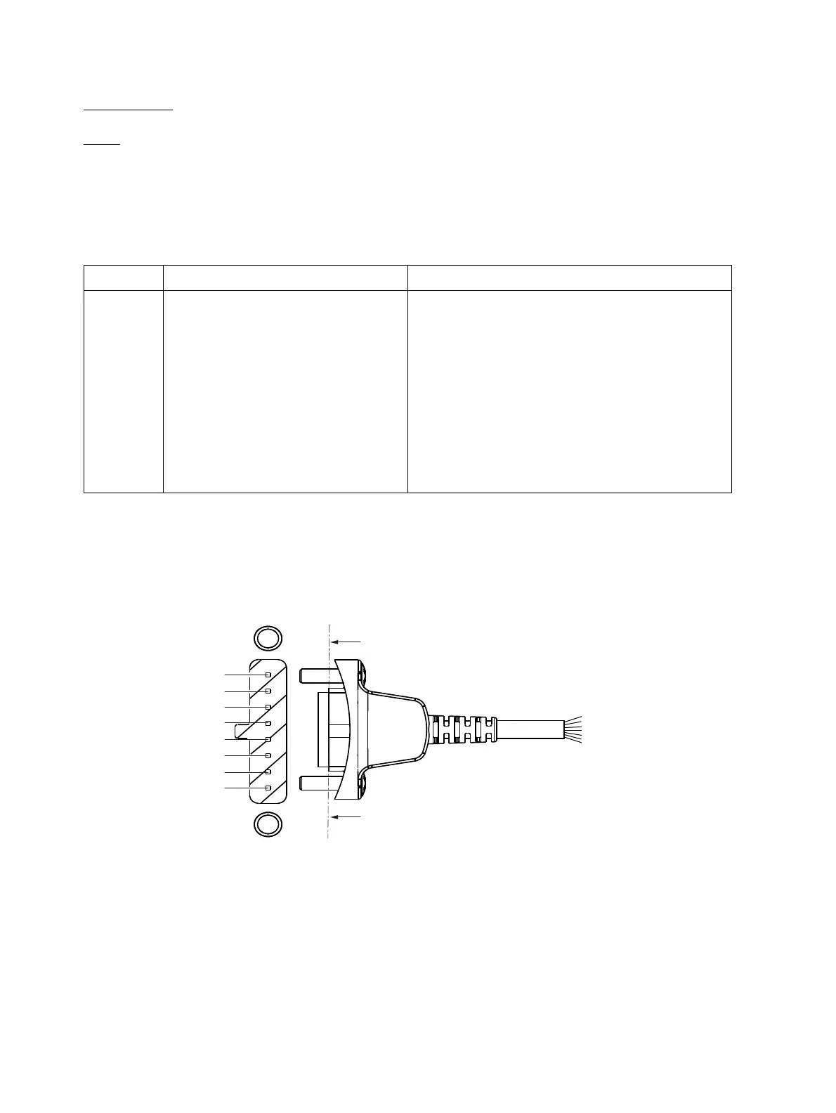
Figure 1003
System connector cable for the HMEC 26 series (non solder side)
PIN CABLE IDENTIFICATION FUNCTION
1 white (wh) Audio left +
2 orange (or) Audio right +
3 brown (br) Factory-made programming line (do not connect !)
4 green (gr) + 3.0 V DC, power supply NoiseGard
™
5 yellow (yl) Factory-made programming line (do not connect !)
6red (rd) Mic +
7blue (bl) Mic –
8 screen (scr) Screen, Audio -, DC-
Table 1002
Cable identification
1
sectional view
sectional view
PCB
2
3
4
5
6
7
8
Oct 30/08