SENNHEISER ELECTRONIC GMBH & CO. KG
COMPONENT MAINTENANCE MANUAL
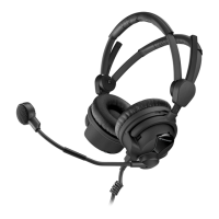
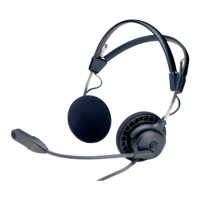
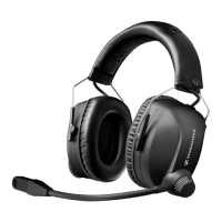
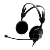
HMEC 26-SERIES
Page 2001
Feb 10/10
23-41-48
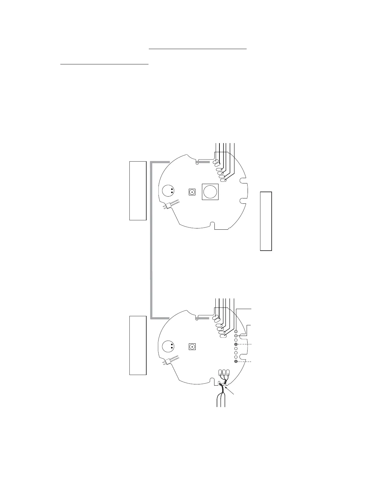
SCHEMATIC AND WIRING DIAGRAMS
1. Schematic and Wiring Diagrams
rd (Mic Hi)
scr *(Mic GND)
bl (Mic Lo)
MICROPHONE
bk (GND)
yl (Prog R)
rd (Supply NoiseGard)
scr * (GND)
bl (Audio R)
HMEC 26: gr (no signal)
HMEC 26-T: gr (TalkThrough-Mute)
Flexible connector
TRANSDUCER /
NoiseGard MIC
HEADBAND
TalkThrough
Microphone
(HMEC 26-T only)
TalkThrough
Microphone
(HMEC 26-T only)
TalkThrough
LED and switch
(HMEC 26-T only)
TalkThrough LED
(HMEC 26-T only)
P301 P301
Flexible connector
TRANSDUCER /
NoiseGard MIC
HEADPHONE CAPSULE,
MICROPHONE SIDE
HEADPHONE CAPSULE,
NON MICROPHONE SIDE
bk (GND)
yl (Prog R)
rd (Supply NoiseGard)
scr * (GND)
bl (Audio R)
HEADBAND
PCB drawn as example
SYSTEM CONNECTOR
(PCBs rear side)
Audio left+
at 1 kHz
NoiseGard
power supply
+3.0 V DC+
Audio right+
at 1 kHz
Audio-,
DC-
strain-relief
strain-relief
HMEC 26: gr (no signal)
HMEC 26-T: gr (TalkThrough-Mute)
* To avoid short circuits cover
the screen with commercial insulation tube.
Strain relief for the microphone cable
Use the strain relief PCB slots (if available)
rd
scr *
bl
Figure 2001
HMEC 26 headphone PCBs
Feb 10/10
Schematic
and
Wiring Dia-
grams