Putting the transmitter into operation
9
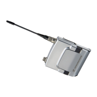
• A 2003 UHF passive directional broadband antenna
• A 1031 passive omni-directional broadband antenna
왘 Use a low-attenuation 50-Ω cable to connect the antenna to the transmitter.
왘 If possible, use a short antenna cable and as little connections as possible, since long
cables and many connectors lead to an attenuation of the antenna signal.
왘 Position the antenna in the same room in which the transmission takes place.
왘 Observe a minimum distance of 1 m between the antenna and metal objects (including
reinforced concrete walls).
Connecting several transmitters to a remote antenna
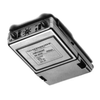
To make multi-channel systems, you should use the AC 3200 antenna combiner (optional
accessory). The AC 3200 allows you to operate up to eight transmitters with a single antenna
without virtually any intermodulation.
왘 Connect the AC 3200 antenna combiner to the BNC socket .
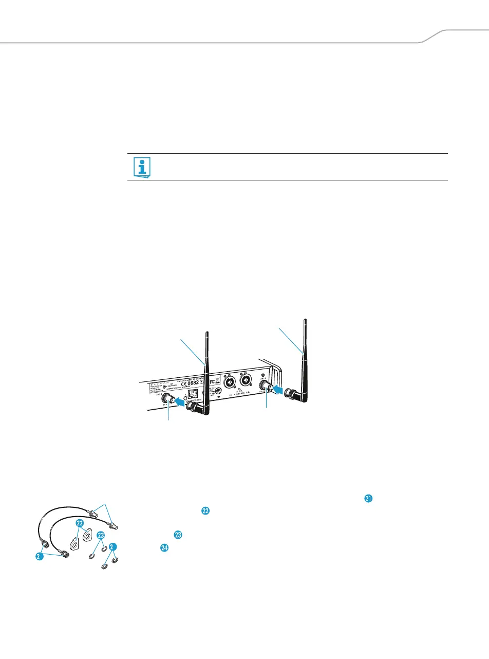
Connecting the rod antenna to the rear of the transmitter
The supplied rod antenna is suitable for all applications where the transmitter is to be put
into operation without a large amount of installation work.
왘 Connect the rod antenna to the BNC socket .
Mounting the antennas to the front of the rack
To mount the antenna connections to the front of the rack when rack mounting the trans-
mitter, you require the GA 3030 AM antenna front mount kit (optional accessory).
The GA 3030 AM consists of:
• 2 BNC extension cables (screw-in BNC socket to BNC connector ),
• 2 antenna holders ,
•4 screws,
•2 washers ,
•2 nuts .
You can connect several transmitters to the same remote antenna (see next section).
1
4