SENS MicroGenius S2/S4 Technical Manual
18
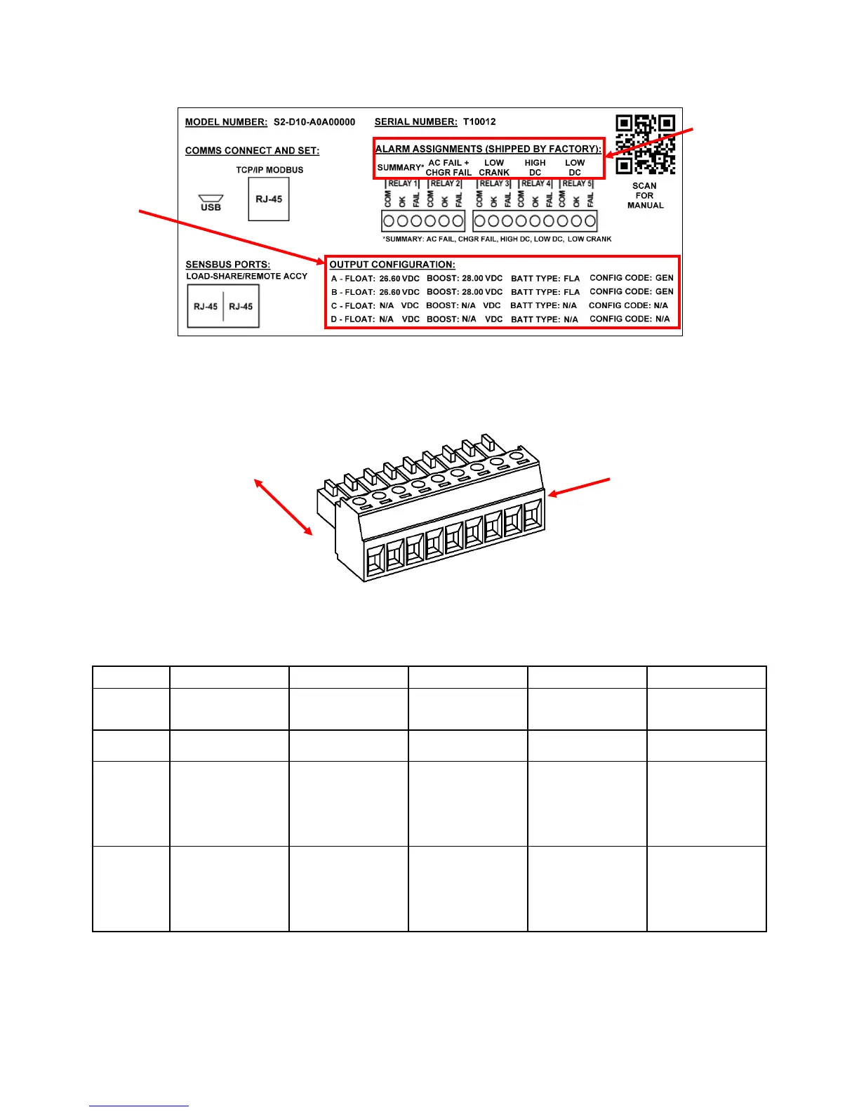
Figure 5 – Configuration Label (on inside lower cover)
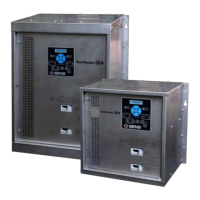
Figure 6 – Pluggable Terminal Block
(TB2 pins 1-9 shown)
Table 7 – Alarm Relay Contact Wiring for Genset Configuration
Wire from COM to OK for alarm present on open circuit or from COM to FAIL for present on closed circuit.
Contacts
Alarm*
Fail Alarm
alarm
(normally
closed)
Defaults to OK
with no AC and
alarm
(normally
open)
FAIL (TB1-3)
Defaults to FAIL
with no AC input
Defaults to FAIL
with no AC input
Defaults to FAIL
with no AC and
Defaults to FAIL
with no AC and
*Summary alarm includes AC Fail, Charger Fail, Low Crank, High DC and Low DC alarms.
PER RELAY:
COM, OK, FAIL
FROM HEADER
battery type and
configuration code
set at the factory
assignments set
at the factory