SENS MicroGenius S2/S4 Technical Manual
42
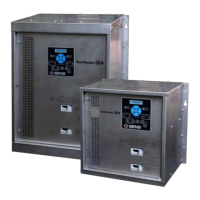
9.14. Remote Alarm/Communications Panel Accessory
The optional remote alarm/communications panel accessory provides additional alarm relay contacts
and the ability to adjust and communicate with multiple chargers using one external device. Connection
of a network cable between the accessory and charger(s) using the SENSbus RJ-45 connectors (see
section 6.10
) automatically initiates communication. For proper operation, a 120-ohm terminator is
required at the ends of the bus. Adjust configuration and view status using the remote panel keypad
and display. See section
9.10 for keypad operation.
10 J1939 COMMUNICATIONS
See data messages below for read-only information available using J1939. Each charger automatically
broadcasts a data message once per second after it has joined the J1939 network. Charger operation
parameters may not be configured using J1939 communications.
In most cases, charger default J1939 settings are sufficient to automatically begin using J1939
communications after connecting the charger to the network. Use the SENS Setup Utility to adjust J1939
settings (e.g. baud rate, vehicle system instance, etc.) if required.
10.1. J1939 Data Messages
0 = OFF, 1 = boost charge, 2 = float charge, 13 = battery
failure/too hot/cold to charge, 14 = charger failure, 15 = no
0 = AC OFF, 1 = AC ON, 2 = sensing error, does not indicate
power out of specification, 3 = no status available
0 = OK, 1 = Fail, 2 = sensor failure, 3 = no status available
0 to 3212.75V in 0.05V increments, 0xFFFF = data not available,
0xFEFF = hardware error
-1600.00 to +1612.75A in 0.05A increments, 0xFFFF = data not
available, 0xFEFF = hardware error
0 = OK, 1 = Fail, 2 = sensor failure, 3 = no status available
0 = OK, 1 = Fail, 2 = sensor failure, 3 = no status available
Low Cranking Voltage
Alarm*
0 = OK, 1 = Fail, 2 = sensor failure, 3 = no status available
0 = OK, 1 = Fail, 2 = sensor failure, 3 = no status available
*Optional, must enable SENS data extensions using SENS Setup Utility