3. NORMAL OPERATOR RESPONSIBILITIES
Long term, reliable system performance depends upon how conscientiously the equipment is operated
and maintained.
Operator responsibilities to assure operation should include the following
recommended practices:
3.1 MAINTAIN OPERATING LOGS
Operators should maintain close control of the process by monitoring system performance
daily. Effluent purity, hardness leakage, service run lengths and pressure drop across the bed
must be recorded faithfully. Since resins are subject to fouling, decrease in product quality or
run length could be the result of fouling. In addition to operating data, log notations should
include chemical delivery dates, equipment design changes, or modifications in program
settings. This information can be invaluable if troubleshooting is ever required.
The daily log should be updated once or twice a shift and should include the following
information:
1. Dates and Time
2. Which softener is on-line
3. Inlet and Outlet pressure gauge readings; calculated pressure drop
4. Influent hardness
5. Effluent hardness
6. Gallon capacity remaining
7. Record salt usage
8. Any equipment design changes, or modifications in programmed cycle settings or capacity
settings
4. OPERATING & REGENERATION PROCEDURES
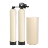
4.1 DESCRIPTION OF OPERATION
The system is designed for fully automatic operation. The twin tank allows the built-in
alternator to switch from the service tank to the stand-by tank. The stand-by tank then
becomes the service tank. The exhausted tank enters regeneration. Service runs will
automatically switch to stand-by tank when the meter set-point has been reached, initiating
the regeneration cycle.
4.2 REGENERATION CYCLE
A. SERVICE
During service flow, raw water passes through the inlet of the control valve and down-
flow through the resin bed, through the lower hub and lateral distribution system, up
the distributor pipe and exits through the outlet of the control valve and into the
service lines. Service flow continues until the preset gallonage has been used,
initiating the regeneration process.
B. BACKWASH
Raw water passes through the inlet of the control valve and is directed down through
the distributor pipe to the bottom of the tank. Water flow passes through the lower hub
and lateral distribution system and travels up-flow through the resin bed. The water
expands the bed scrubbing the resin beads and washing any entrapped dirt out
through the control valve drain port and out to drain. Backwash sequence lasts
approximately 10 minutes.
 Loading...