www.servware.com
800•768•5953
IMPORTANT
Before connecting the equipment to the mains, make sure that it corresponds to the
voltage of the establishment.
Service, Installation & Care Manual
14
2.7 Gas Leak Check
Before lighting the equipment and putting it into operation, check all gaskets on the
gas supply line for leaks. For this, do not use any type of wrench to check for leaks, use
a sudsy soap and water solution.
Follow the steps below for the correct procedure to power on:
1. Turn pilot valves to OFF position by turning adjusting screws clockwise.
2. Turn on the manual gas valve on the inlet side of the gas supply line.
3. Check for gas leaks at the exible coupling or gas connector connection using a
soap solution.
4. In moderation, spray or scrub the solution with soap on gas connections - active
bubbling indicates the location of the gas leak.
5. If a gas leak is detected, turn off the manual gas valve at the inlet side of the gas line.
Call your certied and licensed service technician.
6. If the equipment has no gas leak, continue with the equipment operating instruction.
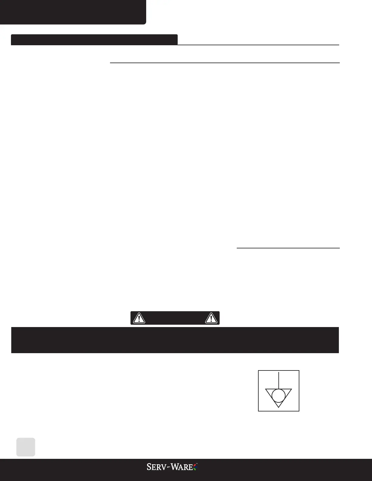
2.8 Electrical Installation (Convection Model)
Make sure that the power supply has the same voltage as the equipment and that the
grounding conductor of the power supply is correctly installed, according to current
legislation. Electrical grounding is important to prevent equipment operators from
having an accident due to electric shock. For protective circuit breakers, they must be as
specied on page 18 in technical data.
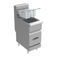
The symbol indicates the equipotential bonding terminal,
designed to connect the equipment via an electrical
conductor to other equipotential bonding points,
such as equipment, counter tops, infrastructures, thus
maintaining the balance between different connection
points, minimizing possible risks of electric shock.
02. EQUIPMENT INSTALLATION