Section 3 Operation
Part Number 020004000 10/13 3-5
Operation Checks and Adjustments
ELECTRONIC ICE AND & CARBONATION CONTROL
Element Function
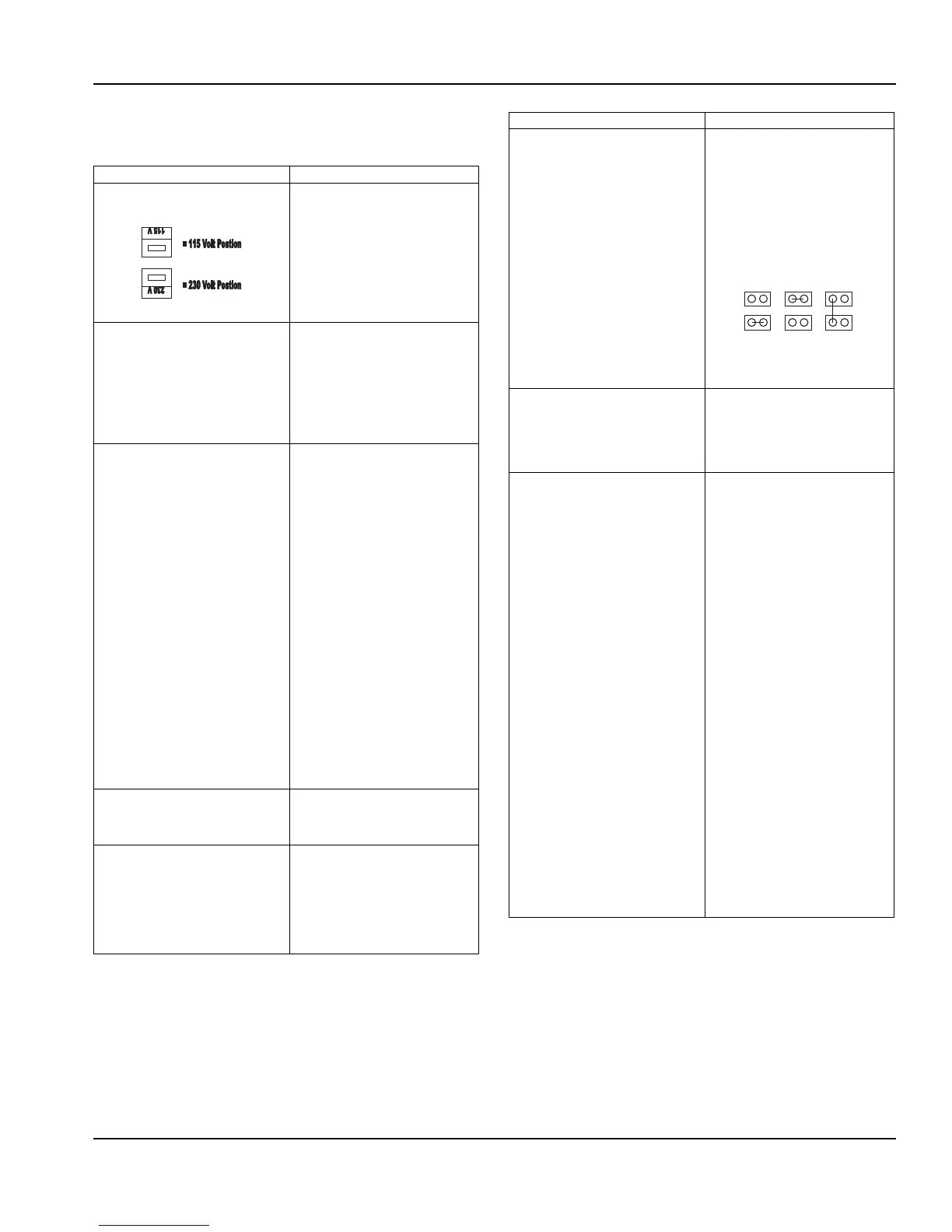
Voltage Selection Switch (Red Side
Switch)
• Switch is used to select voltage,
115 Volt or 230 Volt option.
• When switch is in 115 Volt
position the operating voltages
are 100 Volts 50 Hertz and 120
Volts 60 Hertz.
• When switch is in 230 Volt
position the operating voltages
are 220-240 Volts 50 Hertz and
208-230 Volts 60 Hertz.
On-Off Switch • Switch supplies power to all
control functions.
• When switch is in “on” position
the agitation motor, transformer,
merchandiser bulb and green
power LED will be energized.
(The green power LED will flash
once per second for 5 seconds
then stay on continuously.)
Default Modes – LED/Default (RED)
• RED Carbonator LED = Default
• RED Compressor LED = Default
• If the carbonator motor run time
exceeds the preset fill times,
which are (3) minutes or (7)
minutes. The default mode will
shut power off to carbonator
pump motor for (15) minutes. It
will then activate for one minute
and if the motor does not shut
down within the one-minute
time frame the (15) minute off
time and (1) minute on time
default mode will repeat. The
process will occur a total of (4)
time and then the unit will shut
down, requiring service or a
manual reset. Disconnecting
the power supply from unit or
positioning carbonator switch to
the “off” position and then
returning switch to “on” position
will reset control to normal
operation (only applies to
Internal Carb. units)
• If the ice bank probe does not
detect water in the CEV tub the
refrigeration will shut down and
the compressor LED turn RED.
Carbonator Switch
(Switch in off position for External
Carb. and Juice units, which turns off
green carbonator LED.)
• Switch supplies power to the
carbonator float switch and
green Carbonator LED only.
Green Carbonator LED
(Turned off on External Carb. and
Juice Units)
• The green carbonator LED
illuminates when carbonator
switch is in the on position.
(only applies to Internal Carb.
units).
• The green carbonator LED will
flash rapidly when the
carbonator motor is running.
Carbonator Fill Timing Jumper
(Not used on External Carb. or Juice
Units)
• Carbonator tank fill timing
provides pump failure
protection in the event of water
loss to carbonator pump (only
applies to Internal Carb. units).
• A jumper clip within the control
box sets the three optional time
settings. Units are shipped with
the jumper in (7) minute
position (only applies to Internal
Carb. units).
NOTE: Time tolerance is ±20%.
NOTE: See default mode functions
Green Compressor LED • Illuminates when the
compressor switch is in the on
position.
• Flashes once per second when
the compressor and condenser
fan are energized.
Refrigeration Compressor Output • There are three wires from the
ice bank probe to the control
box. The white wire connects to
the low ice bank probe pin
(probe pin nearest evaporator
coil). All three probe pins must
be immersed in water to initiate
the refrigeration cycle. The
refrigeration system will operate
until the low ice bank probe pin
and center ice bank probe pin
(black wire to the control box) is
covered by ice. The third ice
bank probe pin (probe pin
farthest from evaporator coil) is
the common or ground pin. The
common or ground ice bank
probe pin (green wire to the
control box) should always be
immersed in water and never in
ice of ice bank.
• Note: A delay circuit is built into
compressor and fan motor
circuit. Delay is (4) minutes
(±20%) and will prevent
compressor startup if there is a
power loss to the unit or the
compressor switch is in “off”
position and then placed in “on”
position. Delay will also apply if
refrigeration cycle is stopped on
full ice bank and ice bank probe
sends a faulty signal to restart
refrigeration system within the
(4) minute delay time.
Element Function
J1
3 Minute
7 Minute Unlimited
J1 J1