Switched PDU
Installation and Operations Manual Appendices 153
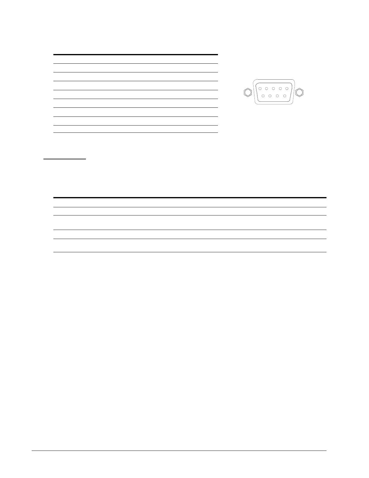
RJ45 to DB9F serial port adapter
Additionally, an RJ45 to DB9F serial port adapter is provided for use in conjunction with the RJ45 crossover cable to
connect to a PC DB9M DCE serial port. The adapter pinouts below reflect use of the adapter with the provided RJ45
crossover cable.
Pin DCE Signal Name Input/Output
1
2 Receive Data RD Output
3 Transmit Data TD Input
4 Data Terminal Ready DTR Input
5 Signal Ground
6 Data Set Ready DSR Output
7 Request to Send RTS Input
8 Clear to Send CTS Output
LED Indicators
Input/Branch/Phase Current
Units are equipped with 7-segment LEDs for reporting of input, branch, or phase current loading. Loading is reported
in amperes and is displayed in
1
/
8
, ½, or 0.1 amp increments under 10A and whole amp increments at and above 10A.
Additionally, the LED can display codes for events detected by the system for immediate local notification.
Behavior/Code Event description
Blinking The unit blinks half-second on, half-second off when the current exceeds the user-defined “high load” or
factory default threshold (80% of maximum Input Feed Capacity).
“oL” Flashes “oL” when the current exceeds the Input Feed Capacity.
FE The PDU has detected an error with the Branch Circuit Protection. For units with a fuse, check to see if the
fuse was blown or removed; for units with a circuit breaker, check to see if the breaker was tripped.
Outlets
Units are equipped with a status LED for each power receptacle. A lit (on) LED indicates that power is being supplied
at the port and a dim (off) LED indicates that there is no power at the port.