6 Introduction Switched PDU
Installation and Operations Manual
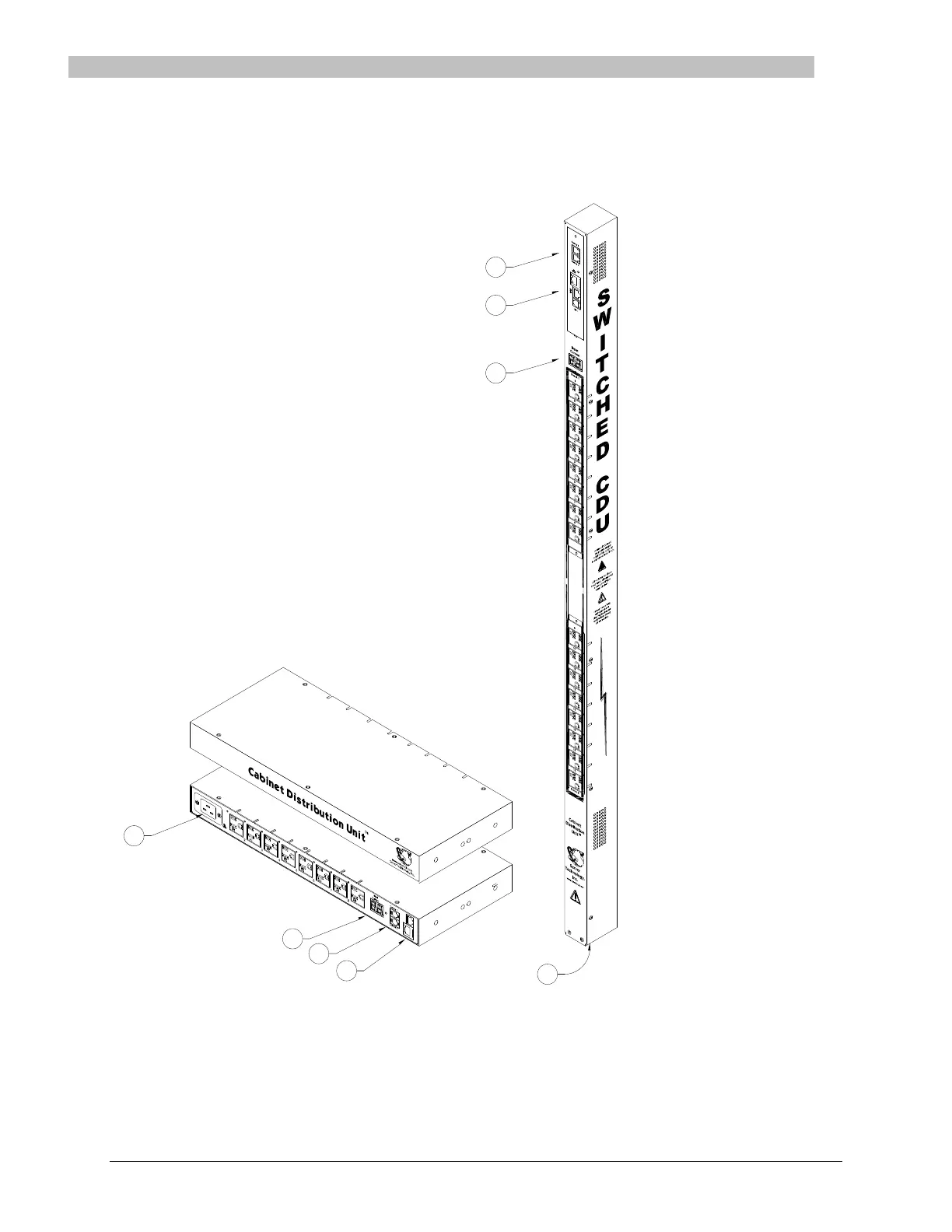
Equipment Overview
1. The power inlet/cord(s) connects the PDU to the electrical power source.
2. The Current LED(s) displays the current load for each infeed, branch or electrical phase per infeed.
3. Two RJ45 connectors for Serial (RS-232) and Ethernet connection.
4. Two mini RJ11 connectors for Temperature/Humidity sensors.
A number is printed above each outlet. These numbers can be used in commands that require an outlet name.