SCORPIO LIGHT SERIES 10’/17’/23’L - CONTROL DISPLAY INFORMATION - Operation menu
Version 1.04 May 26, 2022
50
4.2.4 AUXILIARY
4.2.4.1 BUS CONNECTIONS
In this menu everything connected to the communication line will be
displayed. Also, it is possible to see the Software version for each axis
and, if the number of an axis is pressed, a screen will display more
information referred to that axis.
4.2.4.2 COMMAND ADJUST
It calibrates the cursor of the Hand Command. To calibrate it, press
the limits numbers in the middle of the screen (fig.04.33).
Once the calibration screen appears, move the cursor to both limits
and then press OK. Now the range of movement of the cursor is
introduced to the system. This needs to be done in case the crane
moves faster in one direction than the other.
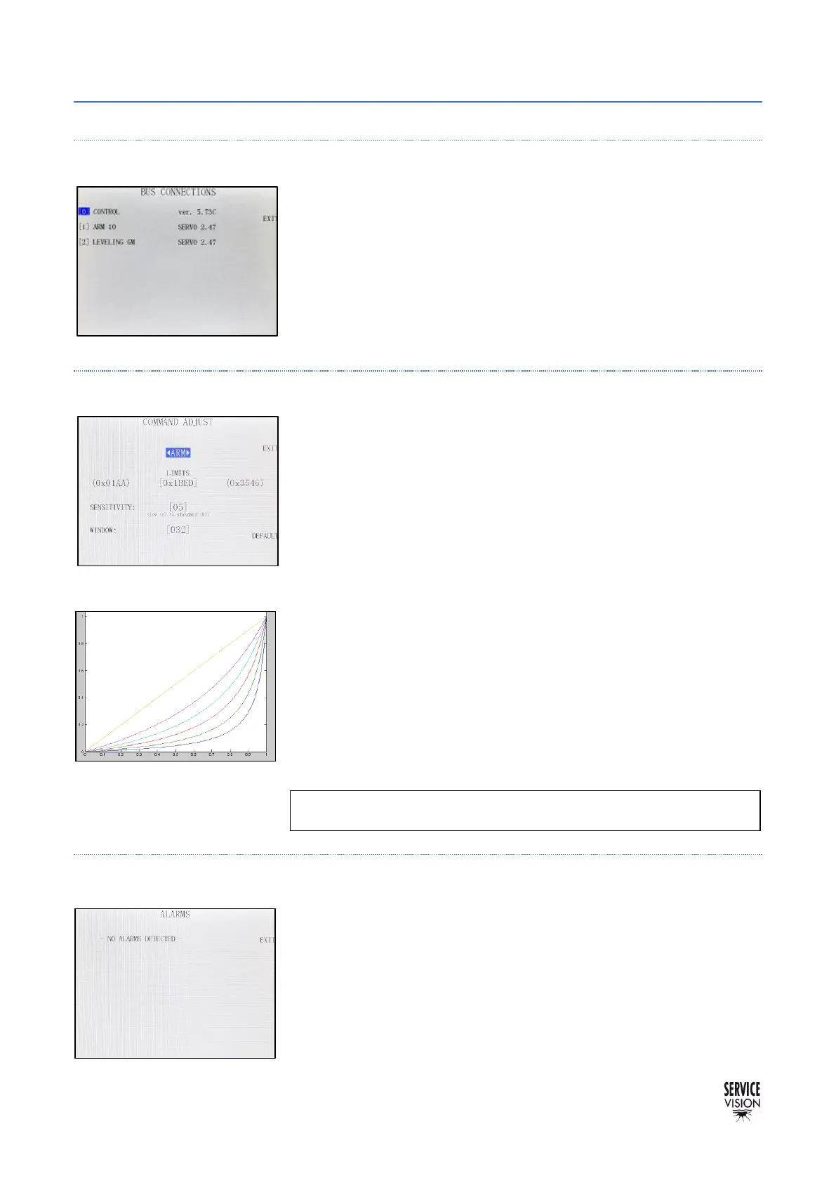
The SENSITIVITY parameter changes the relation between the
cursor from the Hand Command and the speed of the crane. It goes
from a lineal relation (5) to an exponential relation by reducing this
parameter until 0 (fig.04.34). The more is reduced, the more
exponential the relation.
WINDOW is the range of the potentiometer where it can be moved,
and the system will not make any movement on the crane (also known
as dead band).
4.2.4.3 ALARMS
The SCORPIO LIGHT CRANES recognizes a series of different
alarms. In case the temperature of the motor is too high for example,
it will be displayed in this screen.
 Loading...