SCORPIO LIGHT SERIES 10’/17’/23’L - SERVICE & MAINTENANCE - Driver adjustment
Version 1.04 May 26, 2022
SERVICEVISION BIS SL
Ríos Rosas, 20 · 08940 CORNELLA DE LLOBREGAT (Barcelona) Spain · Tel. 34 93 223 86 30 · Fax 34 93 223 86 31 67
comercial@servicevision.es · www.servicevision.es
stop at that exact time. If it is delayed, turn CLOCKWISE this
potentiometer. If it is too stiff, turn it COUNTERCLOCKWISE.
• Potentiometer 4 Test/offset: This potentiometer adjusts the offset
or zero of the motor. Turn the potentiometer until the motor stops
spinning while enabling and disabling the standby button.
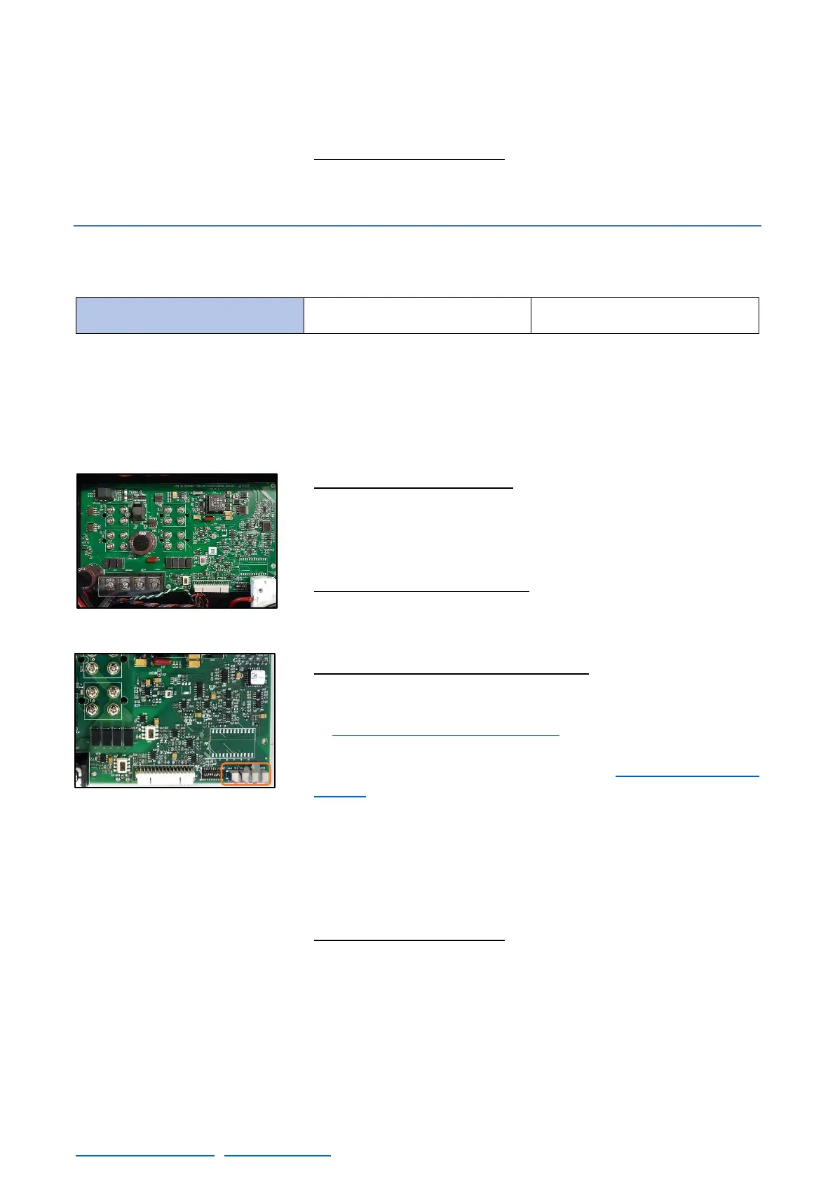
6.7.2 S17’/S23’L ARM DRIVER
There is only one DIP switch in the driver for the S17’/S23’L arm:
Once this is verified, start the crane, and find the magnetic limits of the crane. When the main screen
is shown, the driver can be adjusted.
There are 4 potentiometers in the connectors side (bottom right corner on fig.06.25). These
potentiometers adjust different parameters of the motor behavior and the range of these
potentiometers is 15 turns.
• Potentiometer 1 Loop Gain: Turn the potentiometer number 1
CLOCKWISE until hearing a “coupling” noise from the motor.
From this point, turn counterclockwise now until the “buzz” noise
stops. And from this exact point, keep turning counterclockwise for
1,5 turns more and stop.
• Potentiometer 2 Current Limit: Turn the potentiometer number 2
CLOCKWISE until hearing a “click” noise or during 15 full turns
CLOCKWISE to reach its maximum value. From this point, move
one turn COUNTERCLOCKWISE.
• Potentiometer 3 Ref in Gain / SPEED: To adjust the speed it is
mandatory to DISENGAGE the motor of the crane. Switch off the
Electronic Box and remove the belt from the main motor as seen
in chapter 6.4.1 Belts on the crane. Then change the SERVO I
Switch SAd1 direction to MOTOR FREEWHEEL (1,2,3,4 ON)
(check DIP switches for SERVO I in the other documentation
chapter). Switch on the Electronic Box again and turn the
potentiometer clockwise 15 times then turn counterclockwise
slowly until the noise of the motor changes. With the help of a
multimeter, keep adjusting until the voltage value in the Motor
Power Terminals (MOT A, MOT B) is between 27V and 28V (any
value into this range will be considered as correct). Power off the
Electronic Box and set the SERVO I DIP switch 1 as it was.
• Potentiometer 4 Test/offset: This potentiometer adjusts the offset
or zero of the motor. Turn the potentiometer until the motor stops
spinning while enabling and disabling the standby button.
 Loading...